Technical Reference Guide
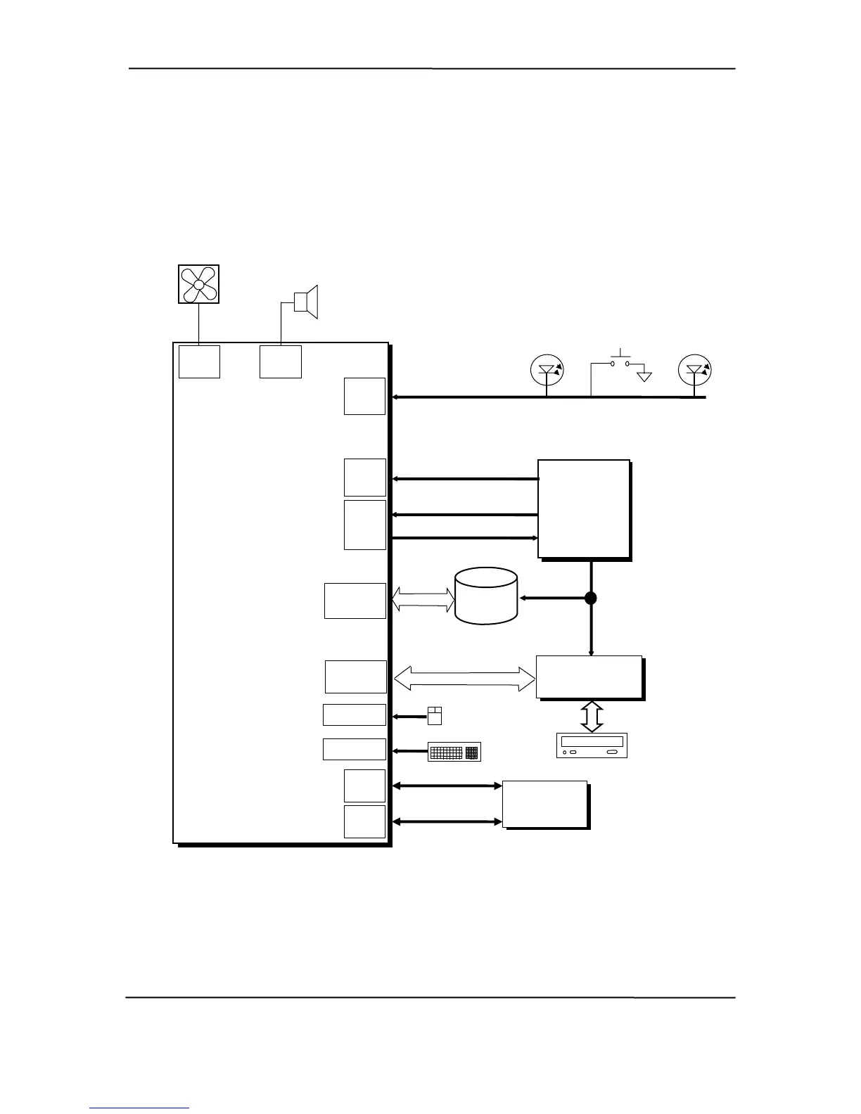
7.4 SIGNAL DISTRIBUTION
Figures 7-6 and 7-7 shows general signal distribution between the main subassemblies of the
system units.
Audio
Fan
PWR
System
Board
(PCA # 332935-001)
Conn.
P6
Conn.
P70
CPU
Fan
Power On/Off
Power On
HD Activity
Pwr Btn, Pwr/HD LED
Conn.
P5 [1]
Conn.
P3
+5, 12 Vcpu
Fan Cntrl., PS On
IDE
Data, Cntl
IDE
Hard Drive
5, 12 VDC
D A
i
Daughter
Board
Multibay
IDE I/F,
, Diskette I/F
3/5/12 VDC, 3/5AUX
Power
Supply
Assembly
Conn.
P1
Pri. IDE
Conn. P20
5, 12 VDC
Multibay
Conn. P21
USB Port
USB Port
Conn.
P23
Mouse
CD-ROM
Front
Panel
I/O Module
USB 4, 5 I/F
Mic In, HP Out Audio
Keyboard
Conn.
P24
OTES: N
[1] See Figure 7-7 for header pinout.
Figure 7-6. USDT Form Factor Signal Distribution Diagram
hp compaq d330 and d530 Series of Personal Computers
Featuring the Intel Pentium 4 Processor
First Edition - June 2003
7-11
 Loading...