Technical Reference Guide
SATA Bus Master Control Registers
The SATA interface can perform PCI bus master operations using the registers listed in Table 5-2.
These registers occupy 16 bytes of variable I/O space set by software and indicated by PCI
configuration register 20h in the previous table. As indicated, these registers are virtually a copy
of those used by EIDE operations discussed in the EIDE section.
Table 5-5. IDE Bus Master Control Registers
Table 5-5.
IDE Bus Master Control Registers
I/O Addr.
Offset
Size
(Bytes)
Register
Default
Value
00h 1 Bus Master IDE Command (Primary) 00h
02h 1 Bus Master IDE Status (Primary) 00h
04h 4 Bus Master IDE Descriptor Pointer (Pri.) 0000 0000h
08h 1 Bus Master IDE Command (Secondary) 00h
0Ah 2 Bus Master IDE Status (Secondary) 00h
0Ch 4 Bus Master IDE Descriptor Pointer (Sec.) 0000 0000h
NOTE:
Unspecified gaps are reserved, will return indeterminate data, and should not be written to.
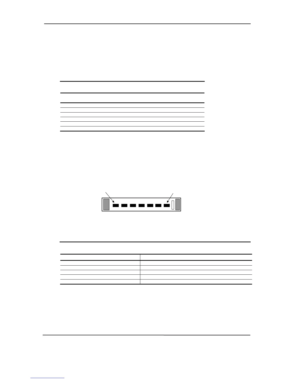
5.2.2.2 SATA CONNECTOR
The 7-pin SATA connector is shown in the figure below.
Pin 1
Pin 7
Figure 5-2. 7-Pin SATA Connector (on system board).
Table 5-6. 7-Pin SATA Connector Pinout
Table 5-6.
7-Pin SATA Connector Pinout
Pin
Description Pin Description
1 Ground 6 RX positive
2 TX positive 7 Ground
3 TX negative 8 Holding clip
4 Ground 9 Holding clip
5 RX negative -- --
hp compaq d330 and d530 Series of Personal Computers
Featuring the Intel Pentium 4 Processor
First Edition – June 2003
5-5
 Loading...