Chapter 4 System Support
4.2 PCI BUS OVERVIEW
NOTE: This section describes the PCI bus in general and highlights bus
implementation in this particular system. For detailed information regarding PCI bus
operation, refer to the PCI Local Bus Specification Revision 2.3.
These systems implement a 32-bit Peripheral Component Interconnect (PCI) bus (spec. 2.3)
operating at 33 MHz. The PCI bus handles address/data transfers through the identification of
devices and functions on the bus. A device is typically defined as a component or slot that resides
on the PCI bus (although some components such as the GMCH and ICH5 are organized as
multiple devices). A function is defined as the end source or target of the bus transaction. A
device may contain one or more functions. In the standard configuration these systems use a
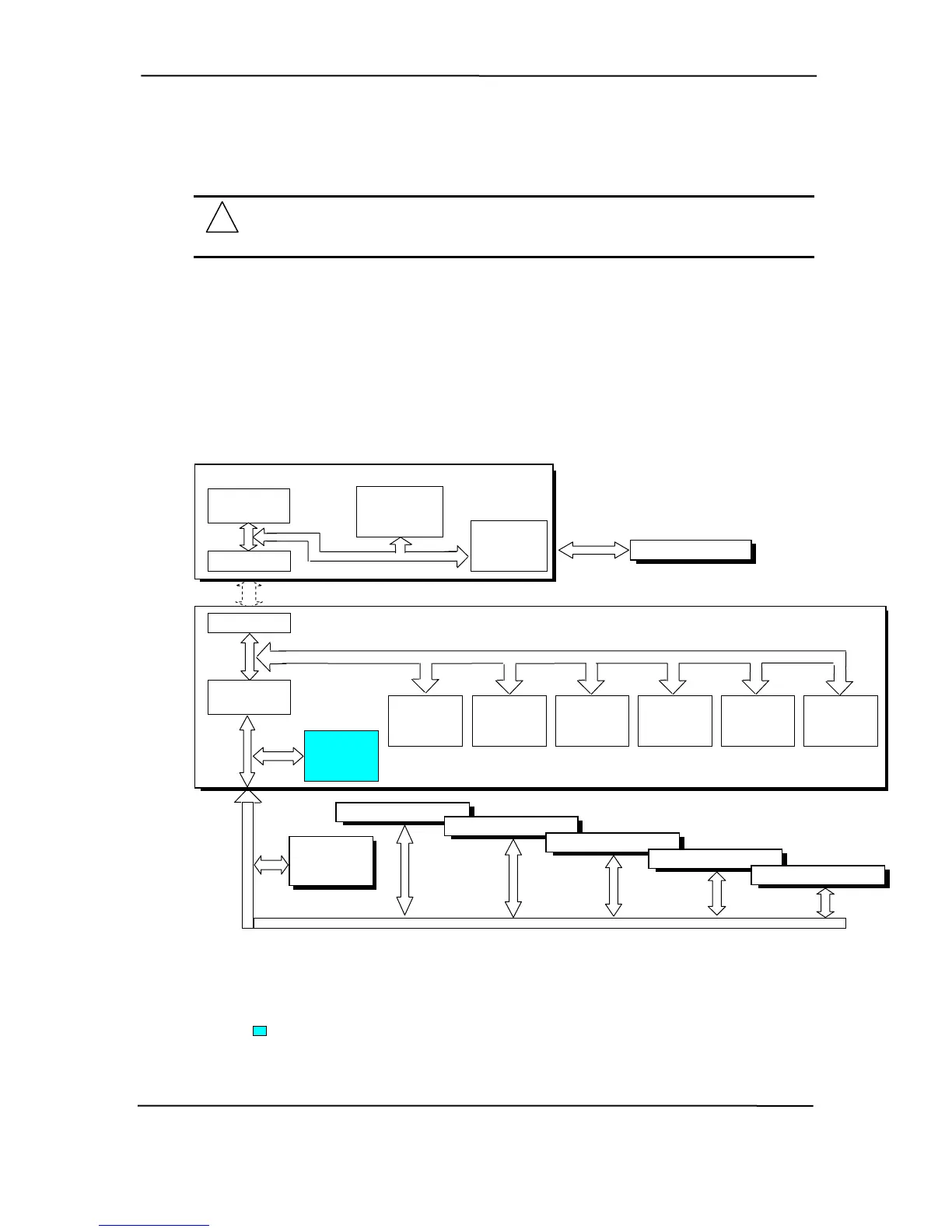
hierarchy of three PCI buses (Figure 4-1). The PCI bus #0 is internal to the chipset components
and is not physically accessible. The AGP bus that services the AGP slot (if present) is designated
as PCI bus #1. All PCI slots and the NIC function internal to the ICH5 reside on PCI bus #2.
Figure 4-1. PCI Bus Devices and Functions
82865G GMCH Component
Integrated
Graphics
Controller
Mem. Cntlr.
Function
PCI
Bus #0
PCI Bus #1
(AGP Bus)
AGP
Bridge
Function
AGP Connector [1]
Hub Link I/F
Hub Link Bus
82801EB ICH5 Component
Hub Link I/F
PCI Bus #0
PCI Bridge
Function
EIDE
Controller
Function
SATA
Controller
Function
USB #1-4
& 2.0
Functions
SMBus
Controller
Function
LPC
Bridge
Function
AC97
Audio
Function
PCI
Bus #5
NIC
I/F
Function
PCI Connector 1
PCI Connector 2 [1]
PCI Connector 3 [2
]
PCI Connector 4 [3]
PCI Connector 5 [3]
Broadcom
B CM
NIC
PCI
Bus #5
NOTES:
[1] ST, SFF, DT, MT, & CMT form factors
rm factors only.
only.
[2] ST, DT, MT, & CMT fo
[3] CMT form factor only.
Not used in these systems.
hp compaq d330 and d530 Series of Personal Computers
Featuring the Intel Pentium 4 Processor
First Edition – June 2003
4-2
 Loading...