Technical Reference Guide
Chapter 5
INPUT/OUTPUT INTERFACES
5. Chapter 5 INPUT/OUTPUT INTERFACES
5.1 INTRODUCTION
This chapter describes the standard (i.e., system board) interfaces that provide input and output
(I/O) porting of data and specifically discusses interfaces that are controlled through I/O-mapped
registers. The following I/O interfaces are covered in this chapter:
♦ Enhanced IDE/SATA interface (5.2) page 5-1
♦ Diskette drive interface (5.3) page 5-6
♦ Serial interfaces (5.4) page 5-10
♦ Parallel interface (5.5) page 5-13
♦ Keyboard/pointing device interface (5.6) page 5-18
♦ Universal serial bus interface (5.7) page 5-24
♦ Audio subsystem (5.8) page 5-28
♦ Network interface controller (5.9) page 5-34
5.2 ENHANCED IDE / SATA INTERFACES
These systems (excepting the USDT form factor) provide both legacy EIDE and the SATA
interfaces. Systems are shipped configured with EIDE drives but can be reconfigured with SATA
devices.
5.2.1 EIDE INTERFACES
Two 40-pin IDE connectors (one for each controller) are included on the system board. Each
controller can be configured independently for the following modes of operation:
♦
♦
♦
Programmed I/O (PIO) mode – CPU controls drive transactions through standard I/O mapped
registers of the IDE drive.
8237 DMA mode – CPU offloads drive transactions using DMA protocol with transfer rates
up to 16 MB/s.
Ultra ATA/100 mode – Preferred bus mastering source-synchronous protocol providing
transfer rates of 100 MB/s.
5.2.1.1 IDE PROGRAMMING
The IDE interface is configured as a PCI device during POST and controlled through I/O-mapped
registers at runtime. Non-DOS (non-Windows) operating systems may require using Setup (F10)
for drive configuration.
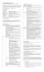
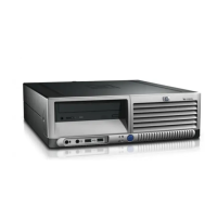
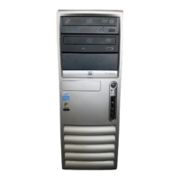
hp compaq d330 and d530 Series of Personal Computers
Featuring the Intel Pentium 4 Processor
First Edition – June 2003
5-1
 Loading...