Technical Reference Guide
7.3 POWER DISTRIBUTION
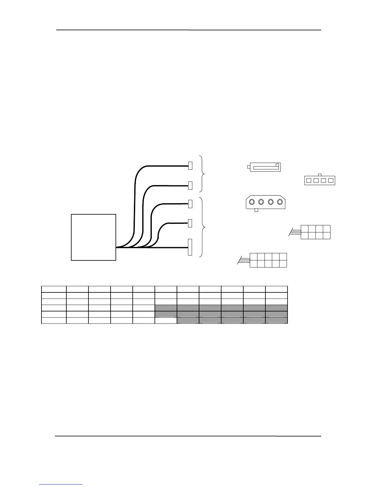
7.3.1 3.3/5/12 VDC DISTRIBUTION
The power supply assembly includes a multi-connector cable assembly that routes +3.3 VDC, +5
VDC, +5 VDC STB, +12 VC, and -12 VDC to the system board as well as to the individual drive
assemblies. Figure 7-2 shows the power supply cabling for the Ultra Slim Desktop form factor.
P5
P1
P5
P4
P2
P3
Power Supply
Assembly
(PN 308446)
P4
5 4 3 2 1
4 3 2 1
To
Drive
Assemblies
P2
1 2 3 4
P1
1
2
5
4
3
6
9
10
7
8
1
2
4
3
8
7
6
P3
5
To
System
Board
Conn. Pin 3 Pin 4 Pin 10 Pin 1 Pin 2 Pin 5 Pin 6 Pin 7 Pin 8 Pin 9
P1 GND NC NC NC +3.3 GND PS On +5 Aux +12 -12
P2 +12 GND GND +5 +12 GND GND +5 NC NC
P3 +12 GND GND +5
P4 JMPR JMPR FS FC
P5 +3.3 +5 GND +12 GND
NOTES:
e.
round)
sense
ed
[1] This row represents pins 13 – 24 of connector P1.
igure 7-2. USDT Power Cable Diagram
Connectors not shown to scal
All + and – values are VDC
.
RTN = Return (signal g
GND = Power ground
RS = Remote
FO = Fan off
FSpd = Fan spe
FS = Fan Sink
FC = Fan Command
F
hp compaq d330 and d530 Series of Personal Computers
Featuring the Intel Pentium 4 Processor
First Edition - June 2003
7-7
 Loading...