Chapter 7 Power and Signal Distribution
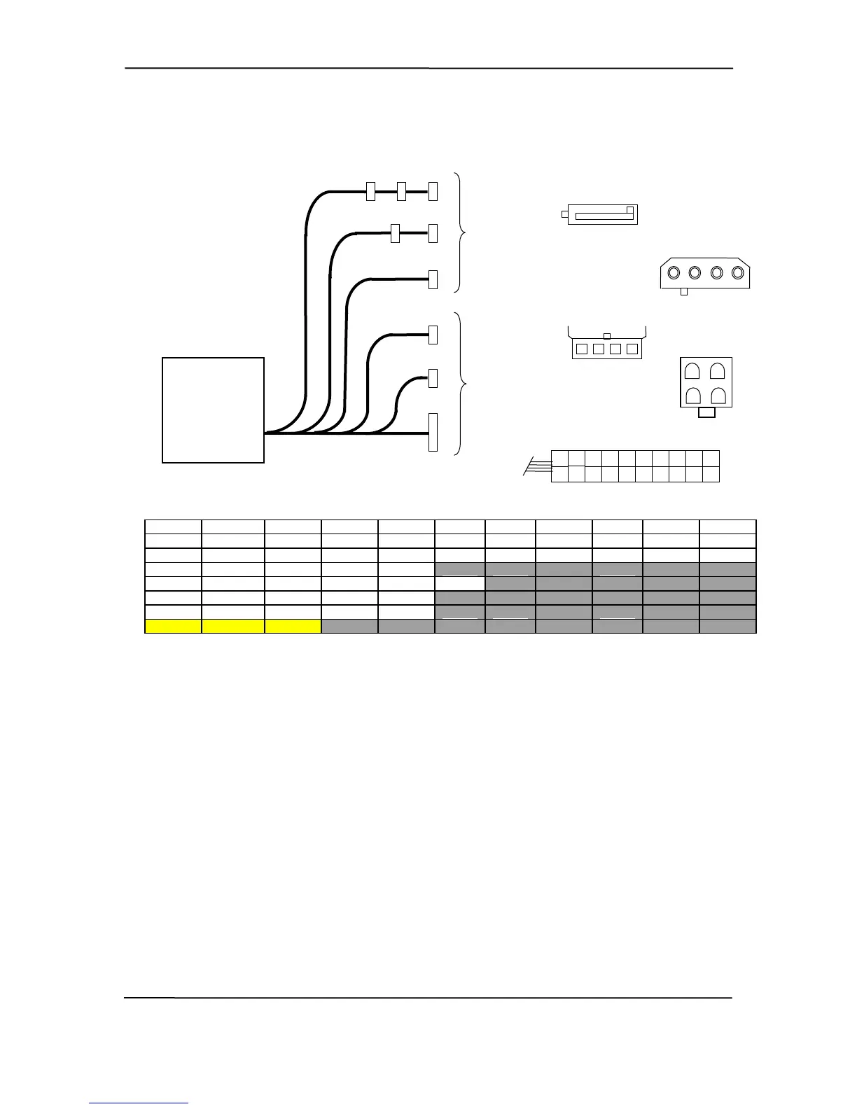
Figure 7-3 show the power supply cabling for the Small Form Factor systems.
Pin 2 Pin 9 Pin 10
er Supply
(PN 308439)
Conn. Pin 1 Pin 3 Pin 4 Pin 5 Pin 6 Pin 7 Pin 8
P1 +3.3 +3.3 RTN +5 R +5 RTN POK +5 ux +12 TN A
P1 [1] +3.3 -12 RTN RTN RTN Open +5 +5 PS On RTN
P2 +5 GND GND +12
P3, P5 +12 +3.3 GND +5 GND
P4, 7, 8 GND +5 +12 GND
P6 GND GND +12.8 +12.8
P9 FS FC
DC
.
ground)
sense
POK = Power OK (power good)
[1] This row represents pins 8 - 14 of connector P1.
Figure 7-3. SFF Power Cable Diagram
Connectors not shown to scale.
All + and - values are V
RTN = Return (signal
GND = Power ground
RS = Remote
FC = Fan command
FO = Fan off
FSpd = Fan speed
FS = Fan Sink
P2
4 3 2 1
To
Drive
Assemblies
P1
System
Board
P8
P4P3
P6
P9
P2
P5
P7
To
P3, P5
5 4 3 2 1
1 2 3 4
P4, P7, P8
P6
4 3
2 1
Pow
Assembly
P1
1
12
1
2
5
4
3
7
6
10
13
8
9
14
15
16
17
18
19
20
1
hp compaq d330 and d530 Series of Personal Computers
Featuring the Intel Pentium 4 Processor
First Edition - June 2003
7-8
 Loading...