Technical Reference Guide
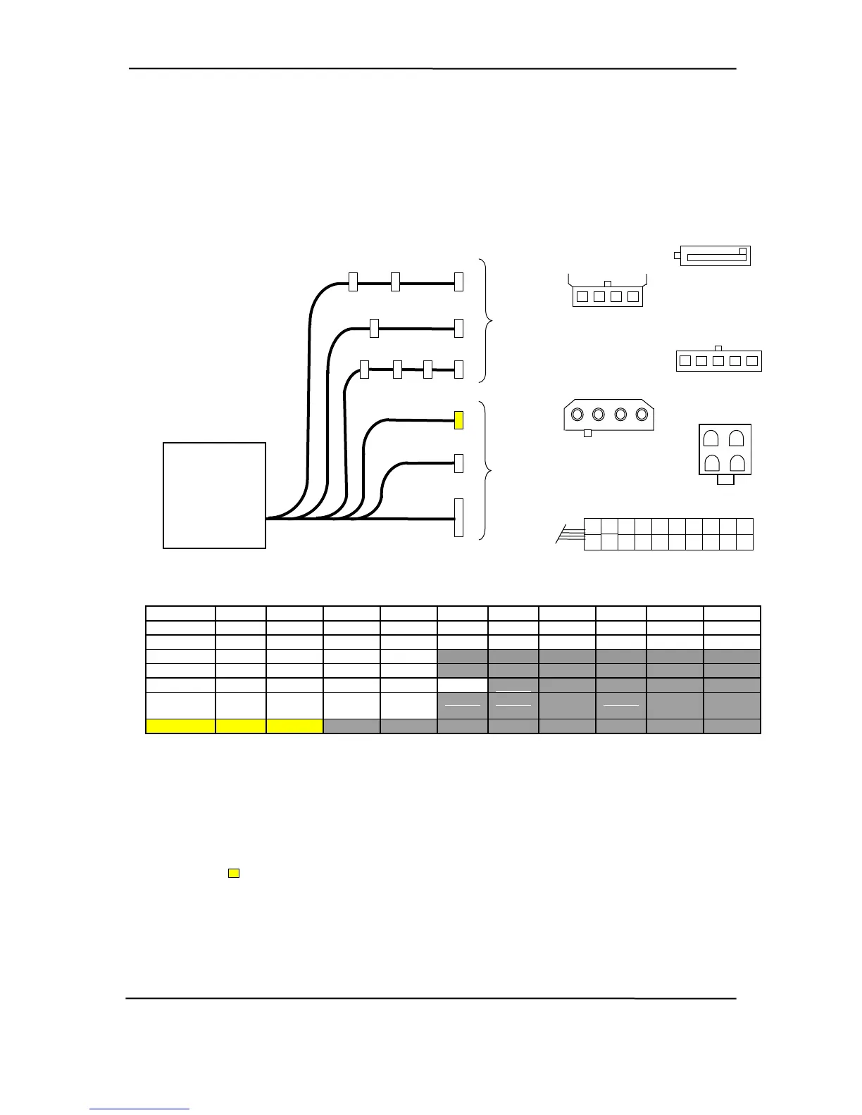
Figure 7-4 shows the power supply cabling for the desktop, microtower, and configurable
minitower systems.
P4-1, P5-1
P7, P8
P2
P10
P8
5 4 3 2 1
To
Drive
Assemblies
P6
P7
4 3 2 1
P3
P4-1
P4
P5
P5-1
5 4 3 2 1
P2, P4 - P6, P10
P9
P3
1 2 3 4
2 1
P3
To
System
Board
Power Supply
Assembly
(PN 308437 )
4 3
P1
P1
6
16
5
15
1
11
12
2
3
13
4
14
7
17
8
18
9
19
10
20
n. Pin 4 Pin 6 Pin 10
Con Pin 1 Pin 2 Pin 3 Pin 5 Pin 7 Pin 8 Pin 9
P1 +3.3 +3.3 RTN +5 RTN +5 RTN POK +5 Aux +12
P1 [1] PS On RTN RTN RTN Open +5 +5 +3.3 -12 RTN
P3 G ND GND +12 +12
P7, 8 +5 GND GND +12
P4-1, 5-1 GND +12 +3.3 GND +5
P2, 4-6, +12 GND GND +5
10
P9 GND FC
NOTES:
le.
round)
er good)
Not connected in these systems. Sink and command functions are handled on system board.
igure 7-4. DT, MT, and CMT Power Cable Diagram
Connectors not shown to sca
All + and - values are VDC
.
RTN = Return (signal g
GND = Power ground
RS = Remote sense
POK = Power ok (pow
FC = Fan Command
[1] This row represents pins 11 - 20 of connector P1.
F
hp compaq d330 and d530 Series of Personal Computers
Featuring the Intel Pentium 4 Processor
First Edition - June 2003
7-9
 Loading...