Page 22-34
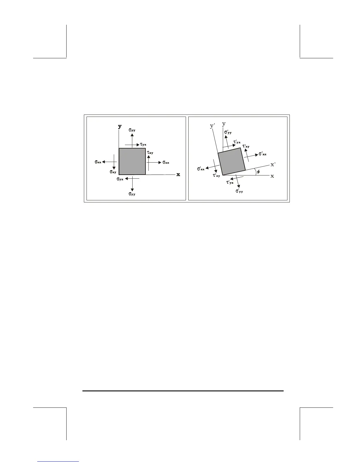
side figure shows the state of stresses when the element is rotated by an angle
φ. In this case, the normal stresses are σ’
xx
and σ’
yy
, while the shear stresses
are τ’
xy
and τ’
yx
.
The relationship between the original state of stresses (σ
xx
, σ
yy
, τ
xy
, τ
yx
) and the
state of stress when the axes are rotated counterclockwise by f (σ’
xx
, σ’
yy
, τ’
xy
,
τ’
yx
), can be represented graphically by the construct shown in the figure
below.
To construct Mohr’s circle we use a Cartesian coordinate system with the x-
axis corresponding to the normal stresses (σ), and the y-axis corresponding to
the shear stresses (τ). Locate the points A(σ
xx
,τ
xy
) and B (σ
yy
, τ
xy
), and draw
the segment AB. The point C where the segment AB crosses the σ
n
axis will
be the center of the circle. Notice that the coordinates of point C are (½⋅(σ
yy
+ σ
xy
), 0). When constructing the circle by hand, you can use a compass to
trace the circle since you know the location of the center C and of two points,
A and B.
Let the segment AC represent the x-axis in the original state of stress. If you
want to determine the state of stress for a set of axes x’-y’, rotated
counterclockwise by an angle φ with respect to the original set of axes x-y,
draw segment A’B’, centered at C and rotated clockwise by and angle 2φ
 Loading...