Chapter 7 Detailed Function Introduction Shenzhen Hpmont Technology Co., Ltd.
- 40 - HD09-S Series User Manual V1.1
Ref. Code Function Description Setting Range [Default]
2: Terminal pulse setting.
• Setting by the terminal pulse input, the maximum input pulse frequency corresponds to the PID setting
100%, check the F16 group parameters.
3: AI1 terminal is setting.
7: Keypad potentiometer is setting.
Feedback access selection
0: Analogue feedback.
• Feedback via terminal AI (F16.01 = 5).
1: Terminal impulse feedback.
• Feedback via DI4 terminal (F15.03 = 53).
Setting para. digital setting
F04.03 define PID regulator preset. F04.01 = 0 (digital reference) effective.
F04.05 Integral time (I) 0.01 - 10.00 [1.00s]
F04.07 Derivative time (D) 0.00 - 10.00 [0.00s]
Differential limiting values
F04.09 Sampling period (T) 0.01 - 50.00 [0.10s]
F04.04, F04.05, F04.07 define process PID parameter.
F04.06 defines the upper limit of the process PID integral term.
F04.08 define proces PID differential terms up limit.
F04.09 define sampling period for feedback quantit. PID regulator will work one time during each period.
• F04.07 = 0, differential items invalid.
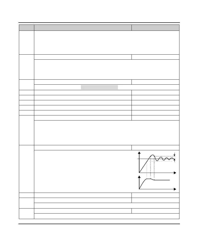
F04.10 Deviation limit 0.0 - 20.0 [0.0%]
Define max. allowable deviation value.
Compared between the system output value and the
process PID value.
• When feedback is within F04.10, PID regulator stop
working. See as right diagram.
• Setting up appropriate F04.10 helps to balance the
system output accuracy and stability.
PID regulator upper limit
PID regulator lower limit
Defines the digital setpoint for the upper / lower output of the process PID regulator.
Define process PID output filtering time.
Feedback value
Pre-given value
Time
Time
Out frequency
F04.10

 Loading...
