Chapter 9 MODBUS Communication Protocol Shenzhen Hpmont Technology Co., Ltd.
- 82 - HD09-S Series User Manual V1.1
9.4 Address Mapping Relationship
9.4.1 Function Parameters Address Mapping
HD09-S function parameter group number is mapped to the high byte of the register address, and the
index within the group is mapped to the low byte of the register address.
F00 - F09 group register address high byte is 0x00 - 0x09, F10 - F15 group register address high byte is
0x0a - 0x0f, F16 - F23 group register address high byte is 0x10 - 0x17, R02 group register address high
byte is 0x1b.
For example: The register address of para F03.02 is 0x0302, and the register address of inverter function
parameter F16.01 is 0x1001.
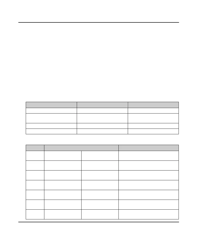
9.4.2 Control Parameters (0x32) Address Mapping
The control group number (0x32) is mapped to the high byte of the register address, and the index in
the group is as follows:
Register address Parameter Saving or not when power off
0x3200 Control command bit Not saving
0x3201 Running frequency setting
Whether it is saved is up to 3rd bit of
F00.14 after power off
0x3202 Auxiliary running frequency setting Not saving
0x3204 Virtual terminal control setting Not saving
The control command byte (0x3200) is defined in the table below.
Control Bit Value and definition Description
Bit0 0: Run command is invalid 1: Run command is valid
Inverter start&stop control (edge trigger
mode)
Bit1 0: Forward 1: Reverse
Running direction, the forward / reverse
rotation of the terminal is valid
Bit2 0: Reserved
1: The stop mode is
deceleration stop
Inverter deceleration stop control (edge
trigger mode)
Bit3 0: Reserved
1: The stop mode is
emergency stop
Inverter emergency stop control (edge
trigger mode)
Bit4 0: Reserved
1: The stop mode is freely
stop
Inverter freely stop control (edge trigger
mode)
Bit5 0: Reserved 1: External fault signal
The inverter displays an external fault and it
stops or continues to run as set by F17.08
Bit6
0: Press and go forward
stop
1: Press and go forward Press and go forward control

 Loading...
