Chapter 7 Detailed Function Introduction Shenzhen Hpmont Technology Co., Ltd.
- 38 - HD09-S Series User Manual V1.1
7.5 F03: Acc. and Dec. Parameter
Ref. Code Function Description Setting Range [Default]
F03.00 Acc. / Dec. mode selection 0,1 [0]
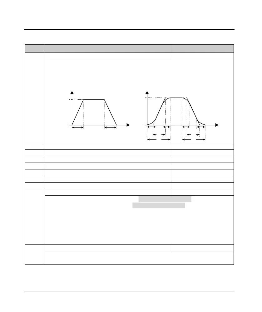
0: Linear Acc. / Dec..
• The output frequency increases or decreases at a constant slope.
1: S curve Acc. and Dec..
• Output frequency increases or decreases according to S curve.
• T5 sets the Acc. time and T7 the actual Acc. time. T6 sets the Dec. time, T8 is the actual Dec. time.
F03.01 Acc.time 1 0.1 - 6000.0 [10.0s]
F03.03 Acc.time 2 0.1 - 6000.0 [10.0s]
F03.05 Acc.time 3 0.1 - 6000.0 [10.0s]
F03.07 Acc.time 4 0.1 - 6000.0 [10.0s]
Acc. time means converter accelerating time from 0 to F00.06 (Max. output frequency) in line mode.
Dec. time means converter decelerating time from F00.06 (Max. output frequency) to 0 in line mode.
Acc. time, Dec. time switch:
• Acc. / Dec. time can be selected by DI terminal 26 or 27 function or F03.09 and F03.10 during inverter
running.
Note: If the brake module is improperly selected, rapid Dec. or load inertia is large, an overvoltage fault may occur
in the inverter; F19.18 can be adjusted by selecting appropriate brake components or increasing the Dec. time and
adjust F19.19 to avoid overvoltage faults that may occur.
Frequency switchover of Acc. Time 2 and 1
When running frequency is lower than F03.09, accelerats in Acc.time 2; Otherwise, speed up in Acc. time.
• It is invalid when terminals are chosed to Acc. and Dec. time (DI are setted as function 26 and 27).
F00.06
Frequency
Time
0
T1:F03.11
T2:F03.12
T3:F03.13
T4:F03.14
T1
T2
T3 T4
T5
T6
T7 T8
F00.06
Frequency
Time
0
Acc. time Dec. time

 Loading...
