Chapter 4 Electrical Installation Shenzhen Hpmont Technology Co., Ltd.
- 14 - HD09-S Series User Manual V1.1
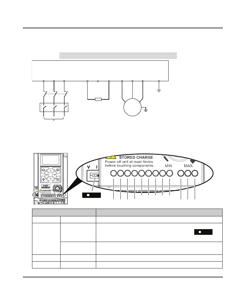
Power Terminal Connection
Power terminal wiring is as shown in following figure.
For selection of contactor, MCBB, power supply cable, motor cable, ground cable and braking resistor,
please refer to section 5.1.1 Wiring Specifications of Input and Output, page 19.
4.3 Control Terminals and Connection
Control Terminals Description
Terminal Description
+10 External power Max. output current100mA
AI
Analogue input
The DIP switch decides the voltage input or current input
• Voltage 0 - 10V, impedance 32kΩ (factory setting)
• Current 0 - 20mA, impedance 500Ω
Digital input
(DI function)
When AI is used as DI, switch signals above 6V can be received
• Function F15.44 is the same with DI1 - DI3 (F15.00 - F15.02)
AO Analogue output Voltage 0 - 10V
GND Power ground Analogue and digital site, 0V
L1 L2
L3/N
(+) BR
U V
W
Braking resistor
HD09-S
MCCB
Contactor
Supply
ground
3~
(-)
PE
M
3~
+10 AI AOGND
DI1 DI2 DI3 DI4 DO
R1A R1B R1C
V I
1
ON
DIP Switch

 Loading...
