Shenzhen Hpmont Technology Co., Ltd. Chapter 7 Detailed Function Introduction
HD09-S Series User Manual V1.1 - 45 -
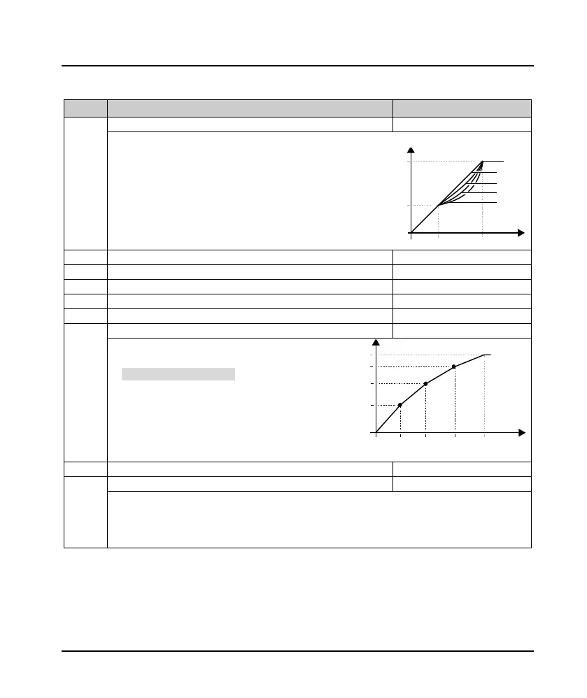
7.10 F09: V/f Controlling Parameter
Ref. Code Function Description Setting Range [Default]
F09.00 Motor V/f curve setting 0 - 4 [0]
Define a variety of V/f settings to meet different load characteristics.
• 4 fixed curves and one custom curve can be selected.
0: Straight line. 0 in the picture.
1: Square curve. Figure 1.
2: 1.2 power curve. Figure 2.
3: 1.7 power curve. Figure 3.
4: User-defined curve.
F09.01 Motor V/f frequency values F3 F09.03 - 100.0% [80.0%]
Motor V/f voltage values V3
F09.03 Motor V/f frequency values F2 F09.05 - F09.01 [50.0%]
Motor V/f voltage values V2
F09.05 Motor V/f frequency values F1 0.0 - F09.03 [0.0%]
Motor V/f voltage values V1
F09.01 - F09.06 is customized V/f curve.
• F09.00 = 4 (user setting curve) is valid.
• Using V1/f1, V2/f2, V3/f3 three-point line way to
define V/f curve, in order to apply to special load
characteristic.
Cut-off points of motor torque increase manually
0.0 - 50.0 (F08.03) [30.0%]
To compensate for the low frequency torque characteristics, we can make some improvement on output
voltage compensation.
• Torque boost is valid in any V/f curve set by F09.00.
• F09.07 ≠ 0, select manual torque boost mode.
0
V
ol
ta
g
e
F
r
eq
uency
0
2
3
1
1/
3
×F
08.
01
1/3
×F08.03
F0
8.01
F0
8.03
F08.03
F08.01
0
F09.02×F08.01
F09.04×F08.01
F09.06×F08.01
F09.05×
F08.03
F09.03×
F08.03
F09.01×
F08.03
Voltage
Frequency
V1,F1
V2,F2
V3,F3

 Loading...
