Shenzhen Hpmont Technology Co., Ltd Chapter 4 Electrical Installation
HD5L Series Controller User Manual ―25―
Wiring of analogue input terminal
The analogue input has three input ports: AI1
-
AI3.
The AI1 is voltage input and the voltage input range is 0
-
10V.The AI2 and the AI3 are selectable
voltage/current input, the input range are -10
-
+10V/0
-
20mA.
The input voltage signal can use the control board of internal +/-10V, or be provided by the
external.
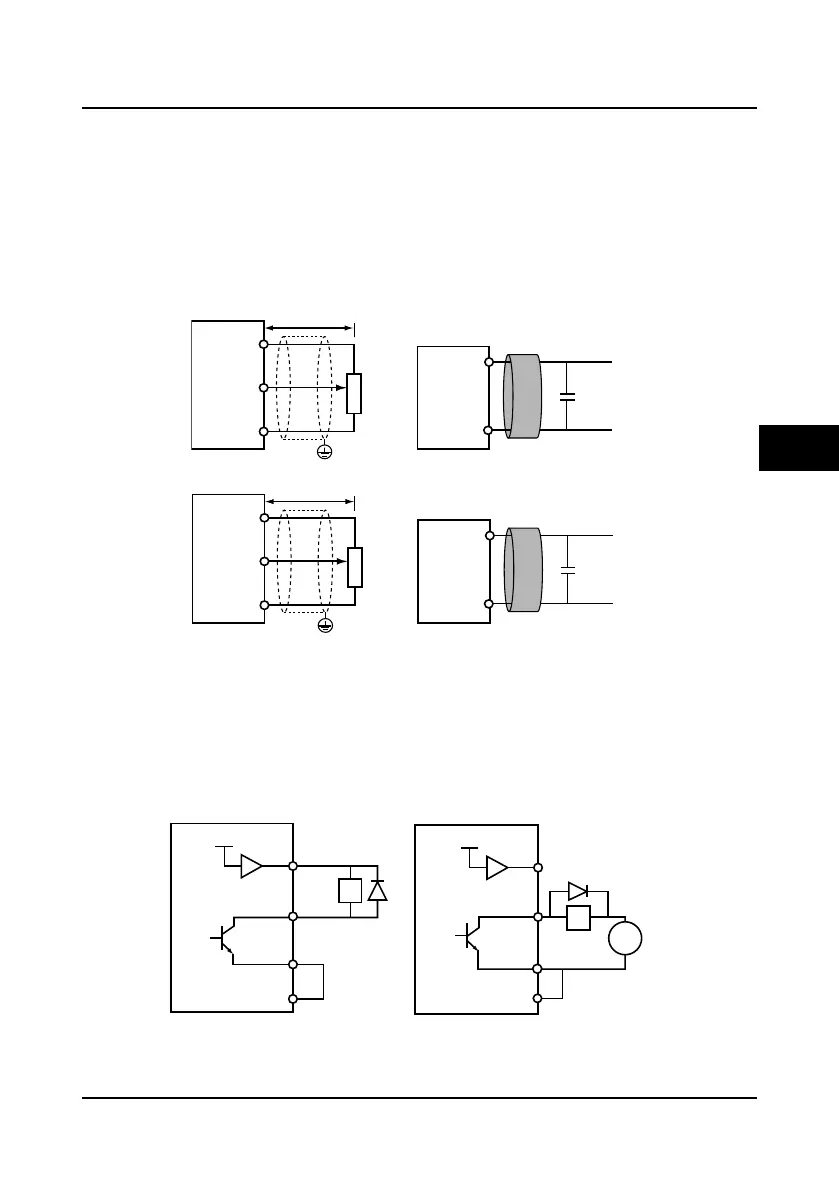
The AI1 input terminal connection and disposal are shown in Figure 4-13. And the AI2 and the
AI3 input terminal connection and disposal are shown in Figure 4-14.
Figure 4-13 AI1 input terminal connection and disposal
Figure 4-14 AI2 and AI3 input terminal connection and disposal
The shielded cable is recommended due to the analogue input signal is electronic signal and
susceptible to external interference. The shielded cable should be no longer than 50m and the
PE should be reliable grounded. In some serious interference state, the analogue input signal
should take the advantage of the filter capacitor and the ferrite core.
Wiring of multi-function output terminal
The function output terminal DO1 and DO2 can use the controller’s internal 24V power supply or
the external power supply. The connections are as shown in Figure 4-15.
Figure 4-15 DO terminal connection
AI1
GND
0.022uF
50V
Less than 50 m
GND
PE
AI1
+10
Ferrite core
Signal line windingonthe
ferritecoreabout 2 or 3 turns
Filter capacitor
Control
Board
Control
Board
Potentiometer
AI2/AI3
GND
0.022uF
50V
GND
AI2/AI3
+10
PE
Less than 50 m
Ferrite core
Signal line windingonthe
ferritecoreabout 2 or 3 turns
Filter capacitor
Control
Board
Control
Board
Potentiometer
DO2
DO1
+ 24V
P24
DO2
DO1
+ 24V
P24
CME
CME
12-30V
DC
COM
COM
+
-
Using theinternal 24V power supply
Relay
coil
Using theexternal power supply
Relay
coil
4

 Loading...