400 Series
EN - 8
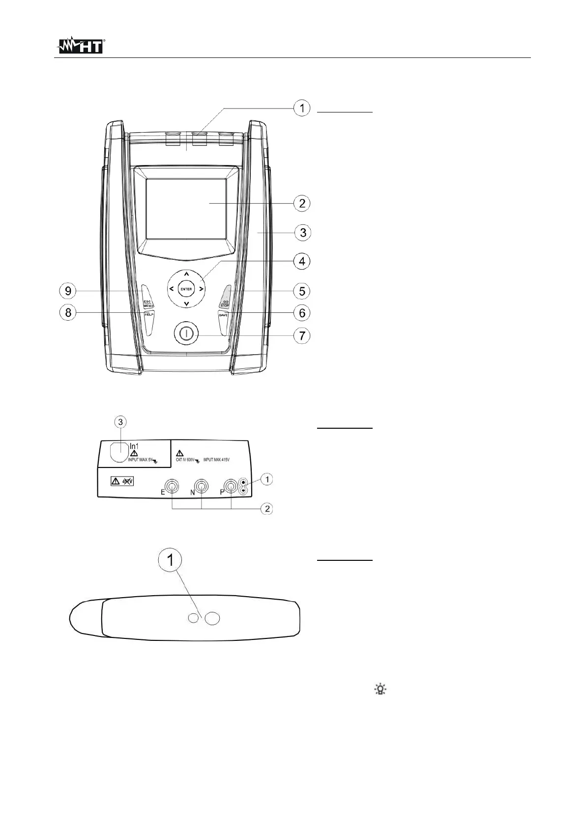
4. NOMENCLATURE
4.1. INSTRUMENT DESCRIPTION
CAPTION:
1. Inputs
2. Display
3. Connector for optoisolated cable
4. ,, , / ENTER key
5. GO/STOP key
6. SAVE key
7. ON/OFF key
8. HELP key
9. ESC/MENU key
Fig. 1: Description of the front part of the instrument
CAPTION:
1. Connector for remote probe
2. E, N, P inputs
3. In1 input
Fig. 2: Description of the upper part of the instrument
CAPTION:
1. Connector for optoisolated cable
Fig. 3: Description of the instrument’s side
4.2. BACKLIGHTING
During instrument operation, a further short pressing of the key turns on the display’s
backlighting (if battery voltage level is sufficiently high). In order to preserve battery efficiency,
backlighting automatically turns off after ca. 20 seconds.
A frequent use of back lighting reduces the batteries’ life.

 Loading...


