EasyManuals Logo

HT 400 Series User Manual

HT 400 Series
88 pages
To Next Page IconTo Next Page
To Previous Page IconTo Previous Page
Page #73 background imageLoading...
Page #73 background image
400 Series
EN - 71
13.2. INSULATION RESISTANCE MEASUREMENT
13.2.1. Purpose of the test
Check that the insulation resistance of the installation complies with the requirements of
IEE 16
th
edition standard.
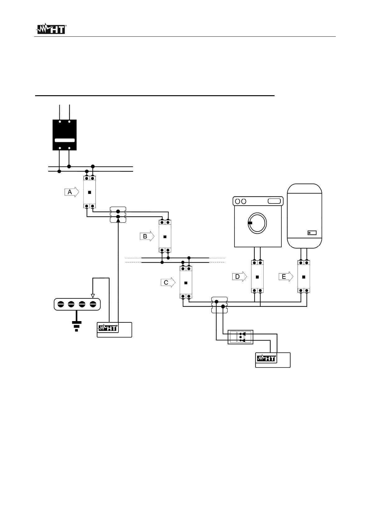
EXAMPLE OF INSULATION MEASUREMENT ON AN INSTALLATION
Fig. 33: Insulation measurements on an installation
The switches D and E are those installed near the load having the purpose of separating it
from the installation. In case the above said RCDs do not exist, or they are monophase, it
is necessary to disconnect the users from the installation before effecting the insulation
resistance test.
A procedure indicating how to effect the insulation resistance measurement on an
installation is reported in Table 3

Table of Contents

Questions and Answers:

Question and Answer IconNeed help?

Do you have a question about the HT 400 Series and is the answer not in the manual?

HT 400 Series Specifications

General IconGeneral
TypeDigital Multimeter
Diode TestYes
Auto RangingYes
Data HoldYes
Operating Temperature0°C to 40°C
DC Current Range400μA to 10A
AC Current Range400μA to 10A
Resistance Range400Ω to 40MΩ
Continuity TestYes
DisplayLCD, 4000 counts
Measurement RangeAs per individual functions

Related product manuals