400 Series
EN - 72
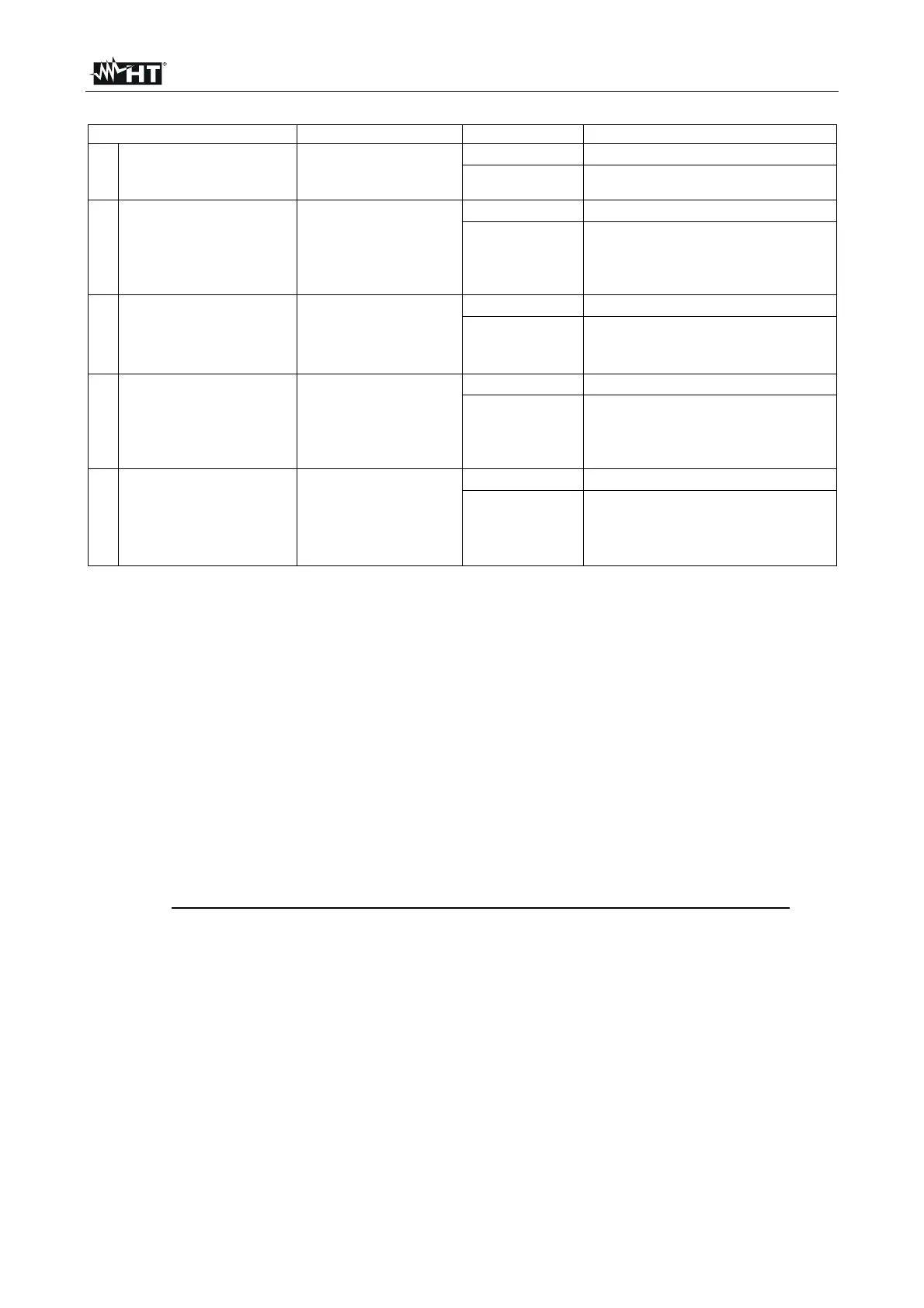
Switch situation Point under test Measurement Judgment on the installation
1.
Turn the switch A, D
and E off
Effect the
measurement on
switch
A
If R
R
LIMIT
OK (
end of the test)
If R R
LIMIT
Proceed 2
2. Turn the switch B off
Effect the
measurement on
switch
A
If R
R
LIMIT
Proceed 3
If R R
LIMIT
The insulation level between A
and B switches is too low, restore
it and effect the measurement
another time
3.
Effect the
measurement on
switch
B
If R
R
LIMIT
OK (
end of the test)
If R R
LIMIT
The insulation level after B
switch is too low
Proceed 4
. Turn the switch C off
Effect the
measurement on
switch
B
If R
R
LIMIT
Proceed 5
If R R
LIMIT
The insulation level between B
and C switches is too low, restore
it and effect the measurement
another time
5.
Effect the
measurement on
switch
C
If R
R
LIMIT
OK (
end of the test)
If RR
LIMIT
The insulation level after B
switch is too low, restore it and
effect the measurement another
time
Table 3: Procedure for insulation measurement referred to the installation reported in Fig. 33
If the circuit is quite large the conductors running side by side make up a capacity which is
to be charged by the instrument in order to carry out a correct measurement; in this case it
is recommended to keep the measurement key pressed (in case a test is effected under
manual mode) until the result gets stable.
When effecting measurements among active conductors it is essential to disconnect all the
users (alarm lamps, intercom transformers, boilers etc) otherwise the instrument will
measure their resistance instead of the installation insulation. Moreover any insulation
resistance test among active conductors could damage them.
The indication "> full scale" warns that the insulation resistance measured by the
instrument is higher than the maximum resistance limit, this result is obviously far higher
than the minimum limits of the above table therefore if during a test this symbol is
displayed the insulation of that point is to be considered in compliance with standards.

 Loading...


