400 Series
EN - 41
6.5.4. P-PE mode in IT systems
6.
Press the GO/STOP key on the instrument or the START key on remote
probe. The instrument will start the measurement.
CAUTION
If message “Measuring…” appears on the display, the instrument is
performing measurement. During this whole stage, do not disconnect the
test leads of the instrument from the mains.
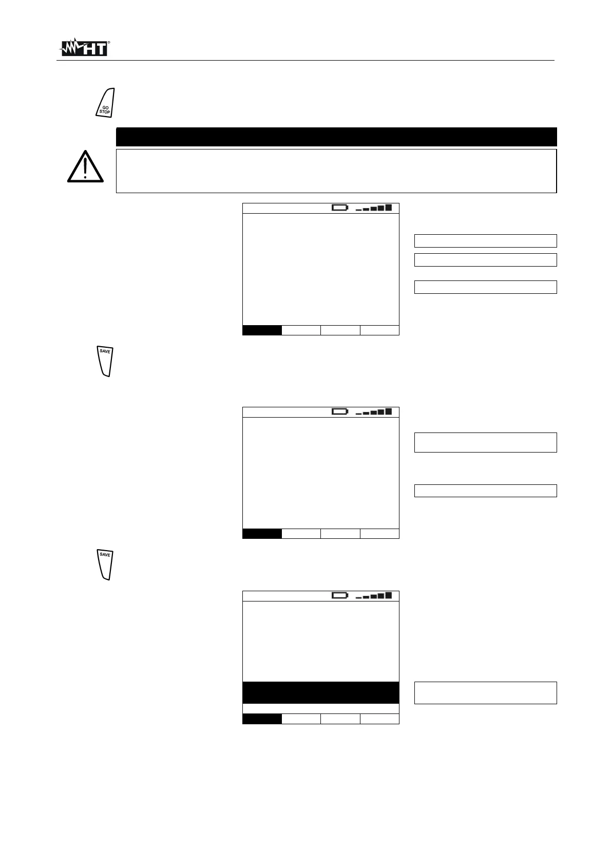
7. Once test is completed, if the
measured contact voltage
value is lower than the set
limit, the instrument gives a
double acoustic signal and
then displays a screen
similar to the one reported
here to the side
LOOP
63mA
Ut=19.7V
FRQ=50.0Hz
VP-N=230V VP-Pe=230V
First earth fault current
Measured contact voltage value
P-N and P-PE measured voltages
P-PE 25V IT
Func UL
8.
The results displayed can be saved by pressing the SAVE key twice or the
SAVE key and, subsequently, the ENTER key (§ 8.1)
6.5.5. Description of anomalous results
1. If the instrument detects an
impedance higher than the
full scale, at the and of the
test it displays the screen
reported here to the side and
gives a long acoustic signal
LOOP
>199.9
---A
FRQ=50.0Hz
VP-P=402V VP-Pe=230V
Impedance value higher than the full
scale
P-P and P-PE measured voltage
P-P STD
Func Mod.
2.
The results displayed can be saved by pressing the SAVE key twice or the
SAVE key and, subsequently, the ENTER key (§ 8.1)
3. If the instrument detects that
the phase and neutral leads
are inverted, the message
reported here to the side is
displayed. Rotate the shuko
plug or check the connection
of the single cables
LOOP
----
---A
FRQ=50.0Hz
VP-N=228V VP-Pe= 1V
REVERSE P-N
The phase and neutral conductors
are inverted
P-N STD
Func Mod.

 Loading...


