400 Series
EN - 6
2. GENERAL DESCRIPTION
2.1. INTRODUCTION
This user manual is referred to the following models ISO410, SPEED418S, COMBI419S,
COMBI420S and COMBI421. Unless otherwise specified, the “instrument” is referred to
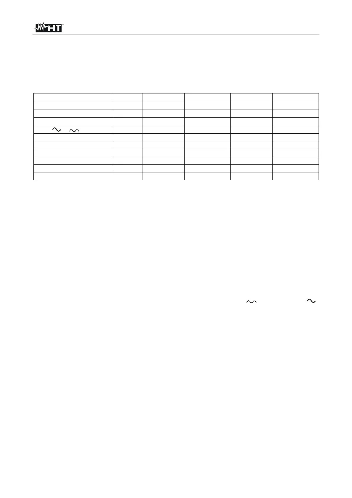
COMBI421 model. The following Table 1 shows the possible measuring functions:
Funzione ISO410 SPEED418S COMBI419S COMBI420S COMBI421
AUTO (Ra + RCD + M)
LOW
M
RCD e
Ra
LOOP
123
AUX
LEAKAGE
POWER
Table 1: Characteristics of models
2.2. INSTRUMENT OPERATION
The instrument can perform following tests (compatibly with the characteristics described
in the table above):
AUTO Test which automatically performs the following test sequence: total
earth resistance through socket, tripping time of the differential switch,
insulation resistance between phase and earth.
LOW Continuity test of earth conductors, protective conductors and equipotential
conductors with test current higher than 200mA and open circuit voltage
between 4V and 24V.
M Insulation resistance measurement with a direct test voltage of 50V, 100V,
250V, 500V or 1000V.
RCD Measurement of following parameters on A-type (
) and AC-type ( )
general and/or selective differential switches with nominal current up to 1A:
tripping time, tripping current, contact voltage (Ut), total earth resistance (RA).
LOOP Measurement of line impedance and fault loop impedance with
calculation of the assumed fault current.
Ra Measurement of total earth resistance with 15mA without causing the
differential protections’ tripping.
123 Indication of the phase sequence.
AUX Measurement of the environmental parameters (temperature, humidity, air
speed and lighting) by means of optional probes.
LEAKAGE Function for measuring leakage current in real time by means of an
(optional) HT96U clamp.
POWER Real-time displaying the values of the electrical quantities in a single-
phase system and the harmonic analysis of voltage and current up to
the 49
th
harmonic with THD% calculation.

 Loading...


