400 Series
EN - 83
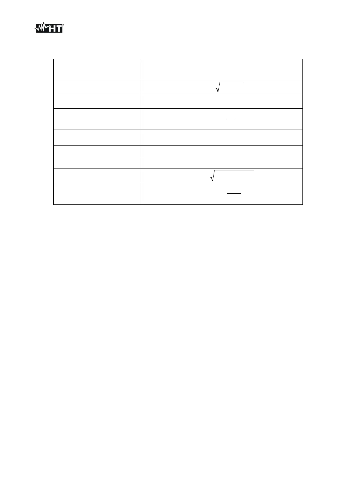
In presence of distorted voltages and currents the previous relations vary as follows:
Phase active power:
(n=1,2,3)
)(IVP
n
k
n
k
n
k
k
n
cos
0
Phase reactive power:
(n=1,2,3)
22
nnn
PSQ
Phase apparent power:
(n=1,2,3)
nnNn
IVS
Phase power factor:
(n=1,2,3)
n
n
n
F
S
P
P
Distorted power factor
(n=1,2,3)
dPF
n
= cosf
1n
= phase displacement between the fundamentals
of voltage and current of n phase
Total active power:
321
PPPP
TOT
Total reactive power:
321
QQQQ
TOT
Total apparent power:
22
TOTTOTTOT
QPS
Total power factor:
TOT
TOT
TOT
F
S
P
P
where: V
kn
= RMS value of k
th
voltage harmonic between n phase and neutral
I
kn
= RMS value of k
th
current harmonic of n phase
f
kn
= Phase displacement angle between k
th
voltage harmonic and kth current
harmonic of n phase
13.10.1. Note
It is to be noted that the expression of the phase reactive power with non sine waveforms,
would be wrong. To understand this, it may be useful to consider that both the presence of
harmonics and the presence of reactive power produce, among other effects, an increase
of line power losses due to the increased current RMS value. With the above given relation
the increasing of power losses due to harmonics is added to that introduced by the
presence of reactive power. In effect, even if the two phenomena contribute together to the
increase of power losses in line, it is not true in general that these causes of the power
losses are in phase between each other and therefore that can be added one to the other
mathematically. The above given relation is justified by the relative simplicity of calculation
of the same and by the relative discrepancy between the value obtained using this relation
and the true value.
It is to be noted moreover, how in case of an electric installation with harmonics, another
parameter called distorted power factor (dPF) is defined. In practice, this parameter
represents the theoretical limit value that can be reached for power factor if all the
harmonics could be eliminated from the electric installation.
13.10.2. Conventions on powers and power factors
As for the recognition of the type of reactive power, of the type of power factor and of the
direction of the active power, the below conventions must be applied. The stated angles
are those of phase-displacement of the current compared to the voltage (for example, in
the first panel the current is in advance from 0° to 90° compared to the voltage):