400 Series
EN - 38
RMT
The virtual RMT key, active only when the Z2Ω mode has been
selected with the MOD key, displays the serial number and the FW
version of the remote unit IMP57
3. If possible, disconnect all loads connected downstream of the measured point, as the
impedance of these users could distort the test results.
4. Use the virtual Mod. key to set the STD test mode.
Should you perform high-resolution tests, recommended
near MT/BT transformers, we suggest using the Z2
mode, which implies the use of the optional accessory
IMP57. Upon the selection of the Z2 mode, the
instrument displays a screen similar to the one reported
here to the side. Connect accessory IMP57 to the
instrument by means of the serial optical cable and
perform the measurements as described in the relevant
user manual.
LOOP
----
----A
FRQ=50.0Hz
VP-N=228V VP-Pe=228V
P-N
Z2
Func Mod.
5. Insert the green, blue and black connectors of the three-pin shuko cable into the
corresponding input leads E, N and P of the instrument. As an alternative, use the
single cables and apply the relevant alligator clips to the free ends of the cables. It is
also possible to use the remote probe by inserting its multipolar connector into the
input lead P. Connect the shuko plug, the alligator clips or the remote probe to the
electrical mains according to Fig. 15, Fig. 16, Fig. 17, Fig. 18 and Fig. 19.
6.5.1. P-N mode
6.
Press the GO/STOP key on the instrument or the START key on remote
probe. The instrument will start the measurement.
CAUTION
If message “Measuring…” appears on the display, the instrument is
performing measurement. During this whole stage, do not disconnect the
test leads of the instrument from the mains.
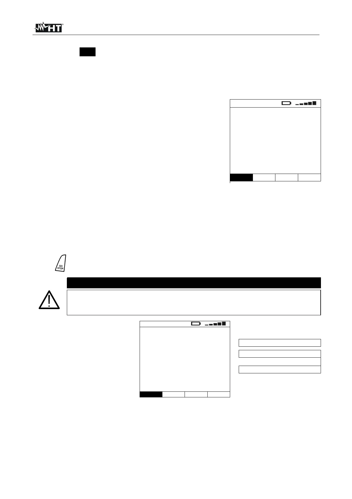
7. Once test is completed, if the
measured impedance value
is lower than the full scale,
the instrument gives a
double acoustic signal and
then displays a screen
similar to the one reported
here to the side
LOOP
1.07
215A
FRQ=50.0Hz
VP-N=228V VP-Pe=228V
Measured impedance value
Prospective short circuit current
P-N and P-PE measured voltages
P-N STD
Func Mod.