400 Series
EN - 36
6.5. LOOP: MEASUREMENT OF LINE/LOOP IMPEDANCE
This function is performed according to standard IEC/EN61557-3 and allows measuring
the line impedance, the earth fault loop impedance and the prospective short circuit
current. The following operating modes are available:
P-N the instrument measures impedance between the phase conductor and the
neutral conductor and calculates the prospective phase-to-neutral short circuit
current
P-P the instrument measures impedance between two phase conductors and
calculates the prospective phase-to-phase short circuit current
P-PE the instrument measures the fault loop impedance and calculates the
prospective fault current
CAUTION
The measurement of line impedance or fault loop impedance involves the
circulation of a maximum current according to the technical specifications of
the instrument (§ 11.1). This could cause the tripping of possible
magnetothermal or differential protections at lower tripping currents.
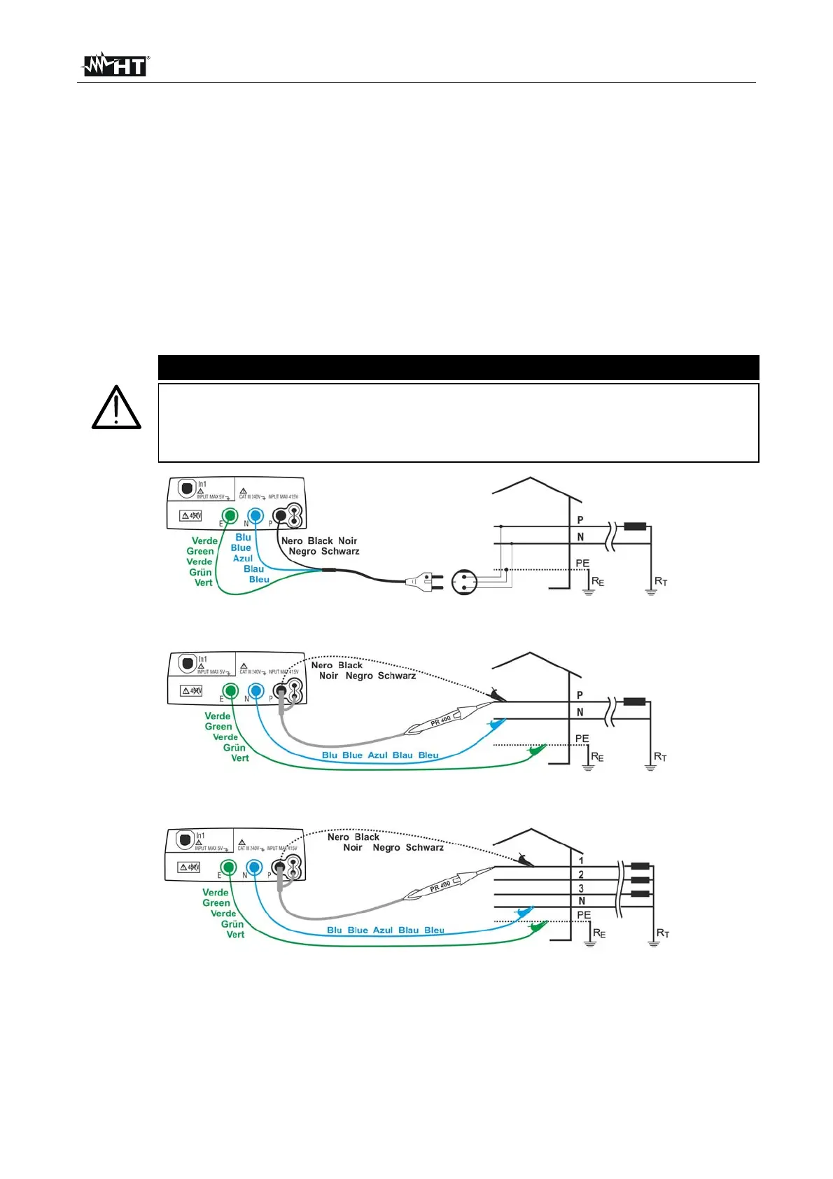
Fig. 15: Instrument connection for 230V single-phase or double-phase P-N line impedance
and P-PE fault loop impedance measurement through shuko cable
Fig. 16: Instrument connection for 230V single-phase or double-phase P-N line impedance
and P-PE fault loop impedance measurement through single cables and remote probe
Fig. 17: Instrument connection for 400V + N + PE three-phase P-N line impedance and
P-PE fault loop impedance measurement through single cables and remote probe

 Loading...


