400 Series
EN - 40
6.5.3. P-PE mode in TT or TN systems
As an alternative:
6.
Press the GO/STOP key on the instrument or the START key on
remote probe once. The instrument will start measuring with a
“0°” type current, injecting a current in phase with the positive
half-wave of voltage
Or:
6.
Press the GO/STOP key on the instrument twice or the START key
on the remote probe before the hyphens disappear. The instrument
will start measuring with a “180°” type current, injecting a current in
phase with the negative half-wave of voltage
CAUTION
If message “Measuring…” appears on the display, the instrument is
performing measurement. During this whole stage, do not disconnect the
test leads of the instrument from the mains.
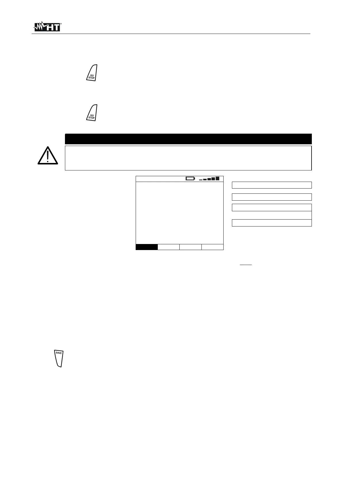
7. Once test is completed, if the
measured impedance value
is lower than the full scale,
the instrument gives a
double acoustic signal and
then displays a screen
similar to the one reported
here to the side
LOOP
0°
1.07
215A
FRQ=50.0Hz
VP-N=230V VP-Pe=230V
0° or 180° type current
Measured impedance value
Prospective short circuit current
P-P and P-PE measured voltages
P-PE STD
Func Mod.
Formula used for calculating the prospective fault current:
PE
N
CC
Z
U
I
where: Z
PE
is the measured fault impedance
U
N
is the nominal phase-to-earth voltage
U
N
= 127V if V
P-PE meas
≤ 150V
U
N
= 230V or U
N
= 240V (§ 5.2.3) if V
P-PE meas
> 150V
8.
9. In TT systems, the impedance value measured by the instrument may only be referred
to the value of the total earth resistance. Therefore, in compliance with the
prescriptions of standard CEI64-8, the measured value may be taken as the value for
the system’s earth resistance
10.
The results displayed can be saved by pressing the SAVE key twice or the
SAVE key and, subsequently, the ENTER key (§ 8.1)

 Loading...


