400 Series
EN - 82
13.9.4. Presence of harmonics: consequences
In general, even harmonics, i.e. the 2
nd
, 4
th
etc., do not cause problems. Triple harmonics,
odd multiples of three, are added on the neutral (instead of cancelling each other) thus
creating a condition of overheating of the wire which is extremely dangerous. Designers
should take into consideration the three issues given below when designing a power
distribution system that will contain harmonic current:
the neutral wire must be of sufficient gauge
the distribution transformer must have an additional cooling system to continue
operating at its rated capacity when not suited to the harmonics. This is necessary
because the harmonic current in the neutral wire of the secondary circuit circulates in
the delta-connected primary circuit. This circulating harmonic current heats up the
transformer
phase harmonic currents are reflected on the primary circuit and continue back to the
power source. This can cause distortion of the voltage wave so that any power factor
correction capacitors on the line can be easily overloaded.
The 5
th
and the 11
th
harmonic contrast the current flow through the motors making its
operation harder and shortening their average life. In general, the higher the ordinal
harmonic number , the smaller its energy is and therefore the impact it will have on the
devices (except for transformers).
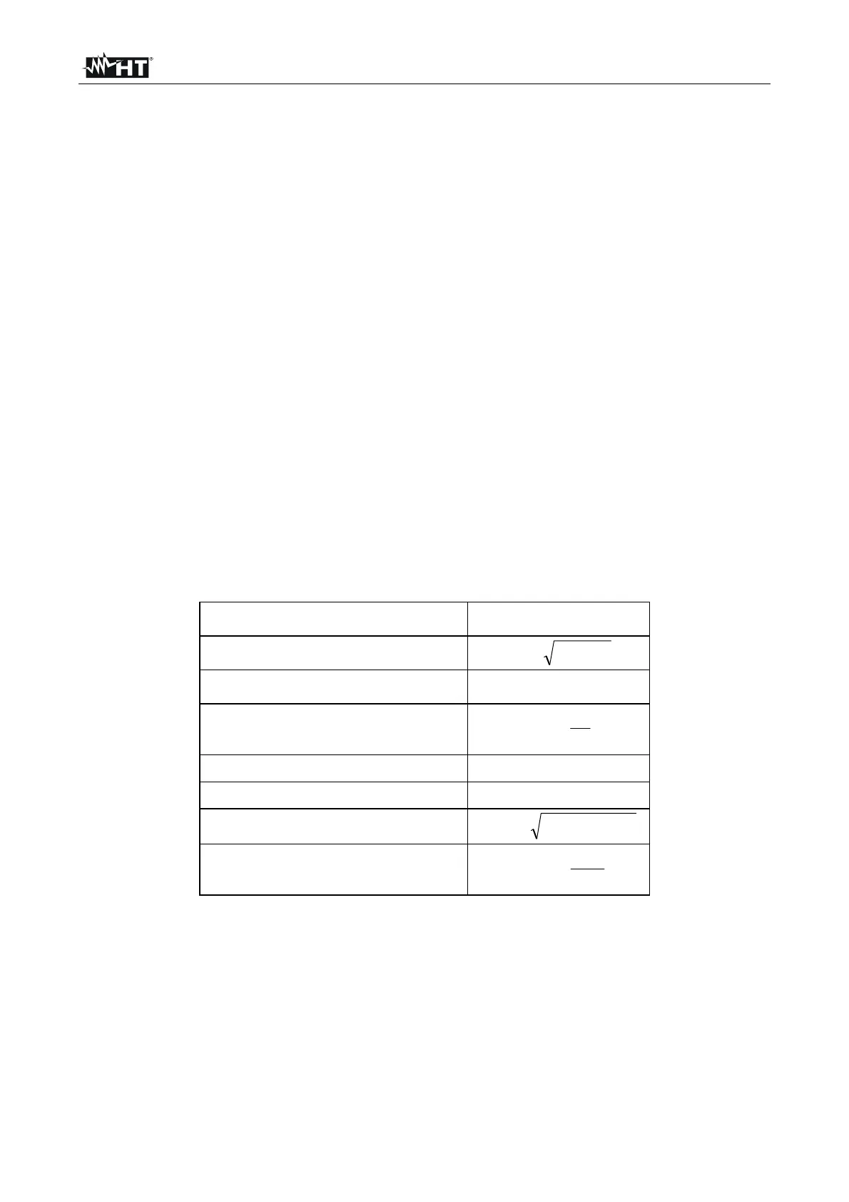
13.10. POWER AND POWER FACTOR DEFINITION
In un generico sistema elettrico, alimentato da una terna di tensioni sinusoidali, si In a
standard electric installation powered by three sine voltages the following is defined:
Phase active power:
(n=1,2,3)
)cos(IVP
nnnNn
Phase reactive power:
(n=1,2,3)
22
nnn
PSQ
Phase apparent power:
(n=1,2,3)
nnNn
IVS
Phase power factor:
(n=1,2,3)
n
n
n
F
S
P
P
Total active power:
321
PPPP
TOT
Total reactive power:
321
QQQQ
TOT
Total apparent power:
22
TOTTOTTOT
QPS
Total power factor:
TOT
TOT
TOT
F
S
P
P
where: V
nN
= RMS value of voltage between phase n and neutral
I
n
= RMS value of n phase current
f
n
= phase displacement angle between voltage and current of n phase

 Loading...


