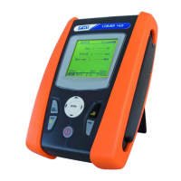
400 Series
EN - 2
6.8.2. Description of anomalous results ........................................................................................... 54
6.9. LEAK: real time measurement of the leakage current through an external clamp .......... 55
6.9.1. Description of anomalous results ........................................................................................... 56
7. MAINS ANALYSIS ...................................................................................................... 57
7.1. PWR: real time measurement of the mains parameters ................................................. 57
7.1.1. PAR mode .............................................................................................................................. 58
7.1.2. HRM V ane HRM I mode ....................................................................................................... 58
8. MEMORY ................................................................................................................... 59
8.1. How to save a measure ................................................................................................... 59
8.1.1. Description of anomalous results ........................................................................................... 59
8.2. Saved data management ................................................................................................ 60
8.2.1. How to recall a measure ........................................................................................................ 60
8.2.2. How to delete the last measure or all of them ....................................................................... 61
8.2.3. Description of anomalous results ........................................................................................... 61
9. CONNECTING THE INSTRUMENT TO THE PC ....................................................... 62
10. MAINTENANCE .......................................................................................................... 63
10.1. General ............................................................................................................................ 63
10.2. Battery replacement ........................................................................................................ 63
10.3. Instrument cleaning ......................................................................................................... 63
10.4. End of life ........................................................................................................................ 63
11. SPECIFICATIONS ...................................................................................................... 64
11.1. Technical feratures .......................................................................................................... 64
11.2. Reference guidelines ....................................................................................................... 68
11.2.1. General .................................................................................................................................. 68
11.2.2. Reference standards for verification measurements ............................................................. 68
11.3. General characteristics .................................................................................................... 68
11.4. ENVIRONMENT .............................................................................................................. 68
11.4.1. Environmental working conditions ......................................................................................... 68
11.5. Accessories ..................................................................................................................... 68
12. SERVICE .................................................................................................................... 69
12.1. Warranty conditions ......................................................................................................... 69
12.2. Service ............................................................................................................................ 69
13. PRACTICAL REPORTS FOR ELECTRICAL TESTS ................................................. 70
13.1. Continuity measurement on protective conductors ......................................................... 70
13.1.1. Purpose of the test ................................................................................................................. 70
13.1.2. Installation parts to be checked ............................................................................................. 70
13.1.3. Allowable values .................................................................................................................... 70
13.2. Insulation resistance measurement ................................................................................. 71
13.2.1. Purpose of the test ................................................................................................................. 71
13.3. Check of the circuit separation ........................................................................................ 74
13.3.1. Definitions .............................................................................................................................. 74
13.3.2. Purpose of the test ................................................................................................................. 74
13.3.3. Installation parts to be checked ............................................................................................. 74
13.3.4. Allowable values .................................................................................................................... 74
13.4. Working test of RCDS ..................................................................................................... 76
13.4.1. Purpose of the test ................................................................................................................. 76
13.4.2. Installation parts to be checked ............................................................................................. 76
13.4.3. Allowable values .................................................................................................................... 76
13.4.4. Note ........................................................................................................................................ 76
13.5. Test of RCD tripping current ............................................................................................ 77
13.5.1. Purpose of the test ................................................................................................................. 77
13.5.2. Installation parts to be checked ............................................................................................. 77
13.5.3. Allowable values .................................................................................................................... 77
13.5.4. Note ........................................................................................................................................ 77
13.6. Measurement of short-circuit impedance ........................................................................ 78
13.6.1. Purpose of the test ................................................................................................................. 78
13.6.2. Installation parts to be checked ............................................................................................. 78
13.6.3. Allowable values .................................................................................................................... 78

 Loading...