GSC60
EN - 133
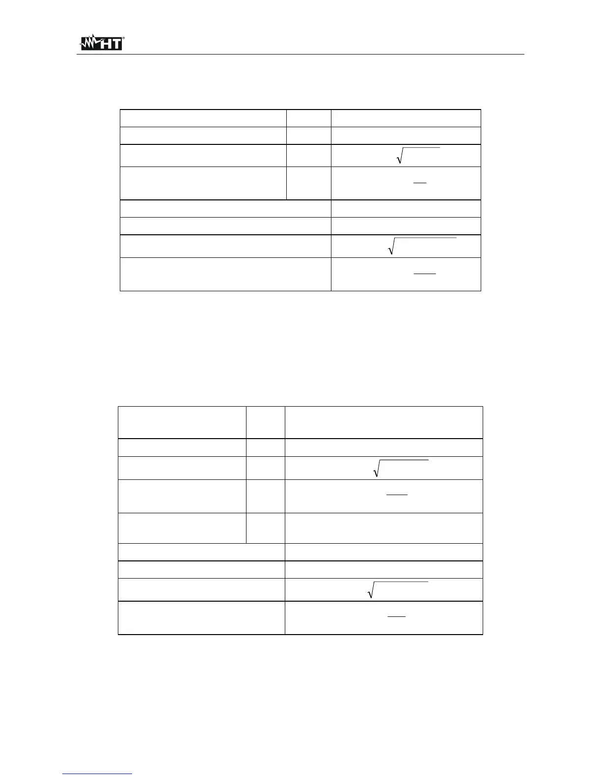
12.16. DEFINITIONS OF POWERS AND POWER FACTORS
In a standard electrical installation powered by three sine voltages the following are to be
defined:
Phase Active Power:
(n=1,2,3)
)cos(IVP
nnnNn
Phase Apparent Power:
(n=1,2,3)
nnNn
IVS
Phase Reactive Power:
(n=1,2,3)
22
nnn
PSQ
Phase Power Factor:
(n=1,2,3)
n
n
n
F
S
P
P
Total Active Power:
321
PPPP
TOT
Total Reactive Power:
321
QQQQ
TOT
Total Apparent Power:
22
TOTTOTTOT
QPS
Total Power Factor:
TOT
TOT
TOT
F
S
P
P
where:
V
nN
= RMS value of voltage between phase n and Neutral.
I
n
= RMS value of n phase current.
f
n
= Phase angle between voltage and current of n phase.
In the presence of distorted voltages and currents the previous relations vary as follows:
Phase Active Power:
(n=1,2,3)
)(IVP
n
k
n
k
n
k
k
actn
cos
0
Phase Apparent Power:
(n=1,2,3)
nnNappn
IVP
Phase Reactive Power:
(n=1,2,3)
22
actnappnreactn
PPP
Phase Power Factor:
(n=1,2,3)
appn
actn
n
F
P
P
P
Distorted Power Factor
(n=1,2,3)
dPF
n
=cosf
1n
= phase displacement between the
fundamentals of voltage and
current of n phase
Total Active Power:
321 actactactact
PPPP
Total Reactive Power:
321 reactreactreactreact
PPPP
Total Apparent Power:
22
reactactapp
PPP
Total Power Factor:
app
act
F
P
P
P
where:
V
kn
= RMS value of kth voltage harmonic between n phase and Neutral.
I
kn
= RMS value of kth current harmonic of n phase.
f
kn
= Phase displacement angle between kth voltage harmonic and kth current harmonic of
n phase