GSC60
EN - 20
6.3. RCD: TEST ON DIFFERENTIAL SWITCHES
This function is performed in compliance with standard IEC/EN61557-6 and allows
measuring the tripping time and current of molded case differential switches of type A ( ),
AC ( ) and B ( ), being General (G), Selective (S) and Delayed ( ). The instrument
allows performing tests on earth leakage relay RCDs with currents up to 10A (with optional
accessory RCDX10).
CAUTION
The instrument can be used for measurements on installations with
overvoltage category CAT IV 300V to earth and max 600V between inputs.
Do not connect the instrument on installations with voltage exceeding the
limits indicated in this manual. Exceeding these limits could cause electrical
shock to the user and damage to the instrument.
lways connect the measuring cables to the instrument and to the alligator
clips with the accessories disconnected from the system
We recommend holding the alligator clip respecting the safety area created
by the hand protection (see § 4.2).
CAUTION
Some combinations of test parameters can be not available in compliance with
the technical specification of the instrument and the RCD tables (see § 10.1 –
the empty cells of RCD tables means not available situations)
The following operating connections are available to perforn the RCD test:
CAUTION
Testing the RCD tripping time causes its tripping. Therefore, check that there
are NO users or loads connected downstream of the differential switch
being tested which could be damaged by a system downtime.
Disconnect all loads connected downstream of the differential switch as they
could produce leakage currents further to those produced by the instrument,
thus invalidating the results of the test.
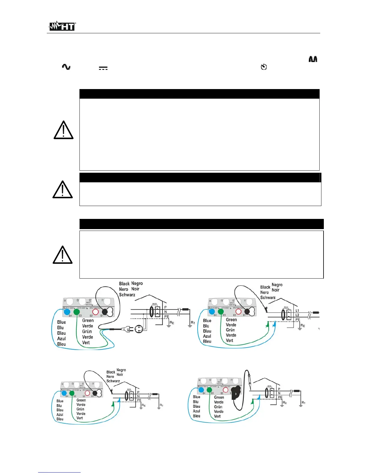
Fig. 10: Connection for single-phase 230V
system by means of shuko plug
Fig. 11: Connection for double-phase
230V with no neutral (no RCD B type)
Fig. 12: Connection for single-phase 230V system with single cables and remote lead