GSC60
EN - 31
6.4. LOOP: LINE IMPEDANCE/LOOP AND OVERALL EARTH RESISTANCE
This function is performed in compliance with standard IEC/EN61557-3 and allows
measuring the line impedance, the fault loop impedance and the prospective short-circuit
current.
CAUTION
The instrument can be used for measurements on installations with
overvoltage category CAT IV 300V to earth and max 600V between inputs.
Do not connect the instrument on installations with voltage exceeding the
limits indicated in this manual. Exceeding these limits could cause electrical
shock to the user and damage to the instrument.
lways connect the measuring cables to the instrument and to the alligator
clips with the accessories disconnected from the system
We recommend holding the alligator clip respecting the safety area created
by the hand protection (see § 4.2).
CAUTION
Depending on the selected electrical system (TT, TN or IT) some kind of
connection and function modes are disabled by the instruments (see Table 2 )
The following operating modes are available
L-N Standard (STD) measurement of the line impedance between the phase
conductor and the neutral conductor and calculation of the assumed phase-to-
neutral short-circuit current. This measurement is carried out even with high
resolution (0.1m) through the optional accessory IMP57.
L-L Standard (STD) measurement of the line impedance between the two phase
conductors and calculation of the assumed phase-to-phase short-circuit current.
This measurement is carried out even with high resolution (0.1m) through the
optional accessory IMP57.
L-PE Standard (STD) measurement of the fault loop impedance between the phase
conductor and the earth conductor and calculation of the assumed phase-to-
earth short-circuit current. This measurement is carried out even with high
resolution (0.1m) through the optional accessory IMP57.
Ra Global earth resistance without causing the differential protections tripping in
systems with and without neutral (see § 12.11)
CAUTION
The measurement of line impedance or fault loop impedance involves the
circulation of a maximum current according to the technical specifications of
the instrument (see § 10.1). This could cause the tripping of possible
magnetothermal or differential protections at lower tripping currents.
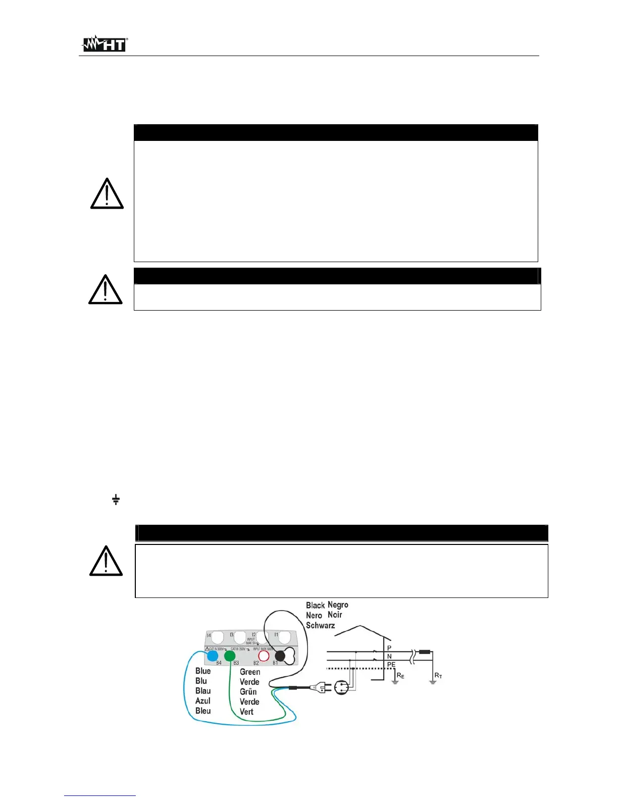
Fig. 17: P-N/P-PE measure for single-phase/two-phase 230V systems with shuko plug