GSC60
EN - 90
5.
Touch the
icon in order to select the pre-set
configuration (see § 12.18) among those made
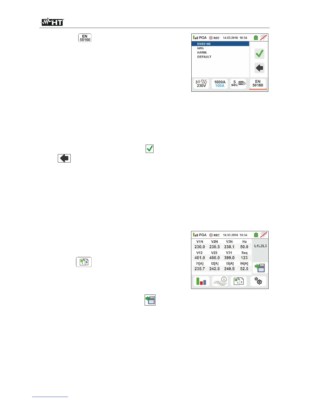
available by the instrument. A screen like the one to the
side is shown. The following options can be selectable:
EN50160 Automatic setting of internal
parameters through the instrument in compliance
with voltage quality network requirements of
guideline EN50160
kWh Automatic setting of internal parameters
through the instrument for the analysis of
power/energy problems
HARM Automatic setting of internal parameters
by the instrument for voltage/current harmonic
analysis
DEFAULT Automatic setting of all recording
parameters
Confirm each setting by touching the icon or touch
the icon to go back to main screen
6.
Insert the connectors of the test cables into the B1, B2, B3, B4 input terminals for
voltage measurements depending on the selected connection type. Insert the remaining
free end of the cables into the corresponding crocodiles or tips. Connect crocodiles or
test leads to phase L1, L2, L3 and N according to the images in § 6.10.1. Connect the
clamps to I1, I2, I3 and I4 inputs and to the phase conductors according to the images
in § 6.10.1. The arrow on the clamp must point in the direction in which the current
normally flows from the generator to the load
6.10.3. Display of measurements
7. The screen like the one to the side shows the numerical
real-time values of electric parameters, referred to a
three-phase 4-wire system. For the meaning of the
parameters, please refer to § 12.16
Touch the icon to show the pages (the number
of which depends on the type of selected connections)
of the TRMS values relevant to total powers, total
power factors and values referred to the single phases
as shown in the following screen
Press the SAVE button or touch the icon to save
the measurement on the display as instantaneous
snapshot (see § 7.1)