GSC60
EN - 78
6.9. ΔV%: VOLTAGE DROP OF MAIN LINES
This feature allows to evaluating the percentage value of voltage drop between two points
of a main line in which a protection device is installed and comparing this value to possible
limit value specified by guidelines. The following modes are available:
L-N Measurement of Phase to Neutral line impedance. The test can be performed
also with high resolution (0.1m) with optional accessory IMP57
L-L Measurement of Phase to Phase line impedance. The test can be performed
also with high resolution (0.1m) with optional accessory IMP57
CAUTION
The instrument can be used for measurements on installations with
overvoltage category CAT IV 300V to earth and max 600V between inputs.
Do not connect the instrument on installations with voltage exceeding the
limits indicated in this manual. Exceeding these limits could cause electrical
shock to the user and damage to the instrument.
lways connect the measuring cables to the instrument and to the alligator
clips with the accessories disconnected from the system
We recommend holding the alligator clip respecting the safety area created
by the hand protection (see § 4.2).
CAUTION
The measurement of line impedance or fault loop impedance involves the
circulation of a maximum current according to the technical specifications of
the instrument (see § 10.1). This could cause the tripping of possible
magnetothermal protections at lower tripping currents.
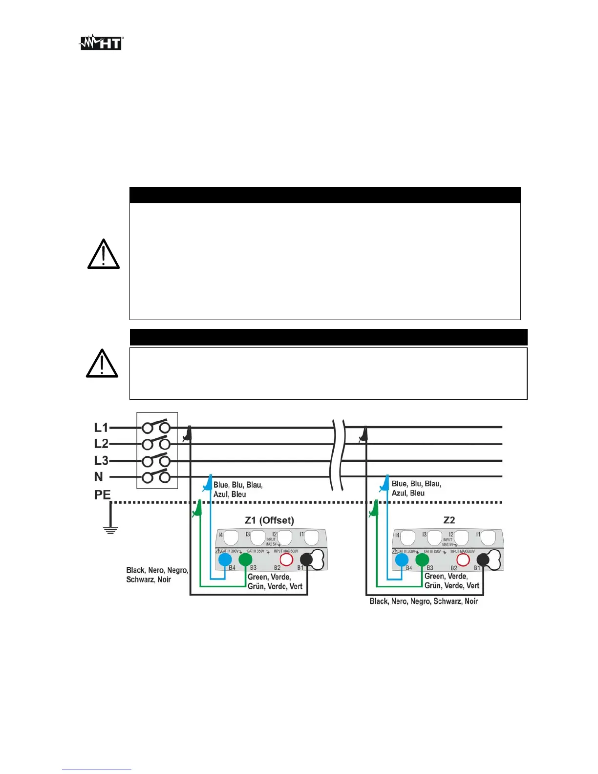
Fig. 33: Connection of the instrument for L-N mode voltage drop measurement