GSC60
EN - 34
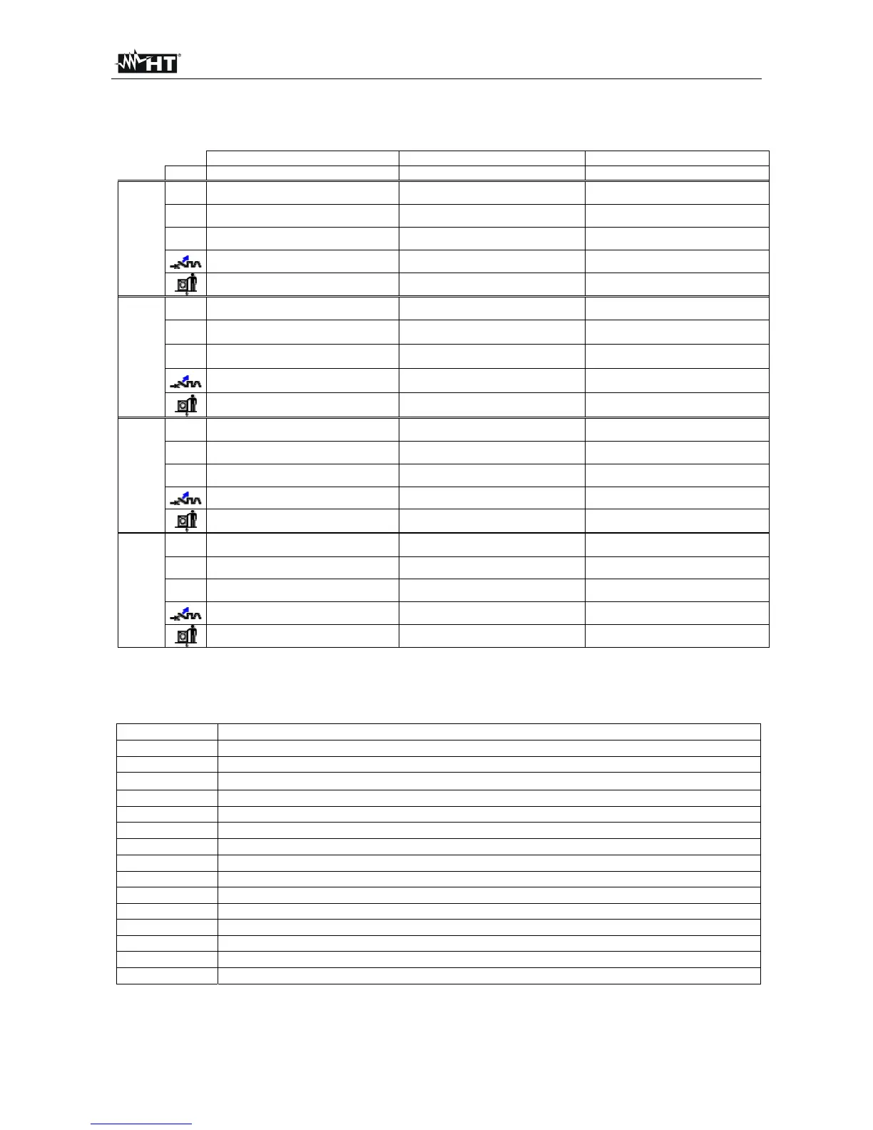
The following table summarizes the possible measures executable depending on the type of
system (TT, TN and IT), of selected modes and the relationships that define limit values
TT TN IT
Mode Condition x OK outcome Condition x OK outcome Condition x OK outcome
L-L
STD
No outcome No outcome No outcome
kA
Isc L-L max < BC Isc L-L max < BC Isc L-L max < BC
I
2
t
(Isc L-L 3F)
2
* t < (K * S)
2
(Isc L-L3F)
2
* t < (K * S)
2
(Isc L-L3F)
2
* t < (K * S)
2
(IscL-Lmin 2F) Tmax Tmax < Tlim (IscL-L min 2F) Tmax Tmax < Tlim (IscL-Lmin 2F) Tmax Tmax < Tlim
L-N
STD
No outcome No outcome No outcome
kA
Isc L-N max < BC Isc L-N max < BC Isc L-N max < BC
I
2
t
(Isc L-N)
2
* t < (K * S)
2
(Isc L-N)
2
* t < (K * S)
2
(Isc L-N)
2
* t < (K * S)
2
(Isc L-N min ) Tmax Tmax < Tlim (Isc L-N min ) Tmax Tmax < Tlim (Isc L-N min ) Tmax Tmax < Tlim
L-PE
STD
No outcome
kA
Isc L-PE max< BC
I
2
t
(Isc L-PE)
2
* t < (K * S)
2
(Isc L-PE min ) Tmax Tmax < Tlim
Tlim Ia Isc L-PE MIN > Ia Utmeas < Utlim
Ra
(No for
IMP57)
STD
kA
I
2
t
(Rameas * Idn) < Utlim Isc L-PE MIN > Idn
Table 2: Conditions of positive outcome depending on the test parameters
Where:
Empty cells Not available mode for this particular combination of electric system
Isc L-L_3F Prospective short circuit current three-phase Phase-Phase (see § 12.5)
Isc L-L_Min2F Prospective short circuit current minimum two-phase Phase-Phase (see § 12.9)
Isc L-N_Max Prospective short circuit current maximum Phase-Neutral (see § 12.5)
Isc L-N_Min Prospective short circuit current minimum Phase-Neutral (see § 12.9)
Isc L-PE_Max Prospective short circuit current maximum Phase-PE (see § 12.5)
Isc L-PE_Min Prospective short circuit current minimum Phase-PE (see § 12.9)
BC Breaking Capacity of the protection device - kA)
K Constant relative to the I2t measurement (vedere § 12.10)
S Section of conductor
Tmax Maximum trip out time of the protection device
Tlim Limit time of fault extinction by the protection set by the user
Ut meas Contact voltage measured
Ut lim Contact voltage limit (25V or 50V)
Ra meas Global earth resistance measured
Idn Trip out current of RCD devices