GSC60
EN - 47
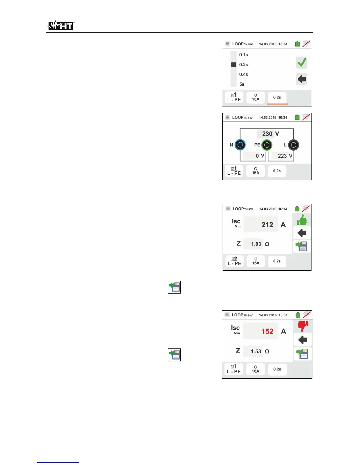
5. Move the slide bar reference by selecting the protection
tripping time between the options: 0.1s, 0.2s, 0.4s, 5s.
Confirm the choice by going back to the initial
measurement screen
6. If possible, disconnect all loads connected downstream
of the measured point, as the impedance of these users
could distort the test results. Connect the alligator clips
or the remote lead to the electrical mains according to
Fig. 17, Fig. 18, Fig. 19 and
Fig. 21 in the farthest possible point respect the
protection on test.
Note the presence of the correct voltage values
between L-N and L-PE corresponding to the selections
carried out in the initial phase (see § 5.1.4) as shown in
the screen to the side.
7.
Press the GO/STOP key for 2s or the START key on
the remote lead. During this whole stage, do not
disconnect the measuring leads of the instrument from
the system under test.
In case of positive result (calculated minimum short-
circuit current HIGHER than tripping current of the
protection device within the specified time – see §
12.6), the screen to the side is displayed by the
instrument
Press the SAVE button or touch the
icon to save
the measurement (see § 7.1).
8. In case of negative result (calculated minimum short-
circuit current LOWER than tripping current of the
protection device within the specified time – see §
12.6), the screen to the side is displayed by the
instrument
Press the SAVE button or touch the icon to save
the measurement (see § 7.1).