GSC60
EN - 52
4.
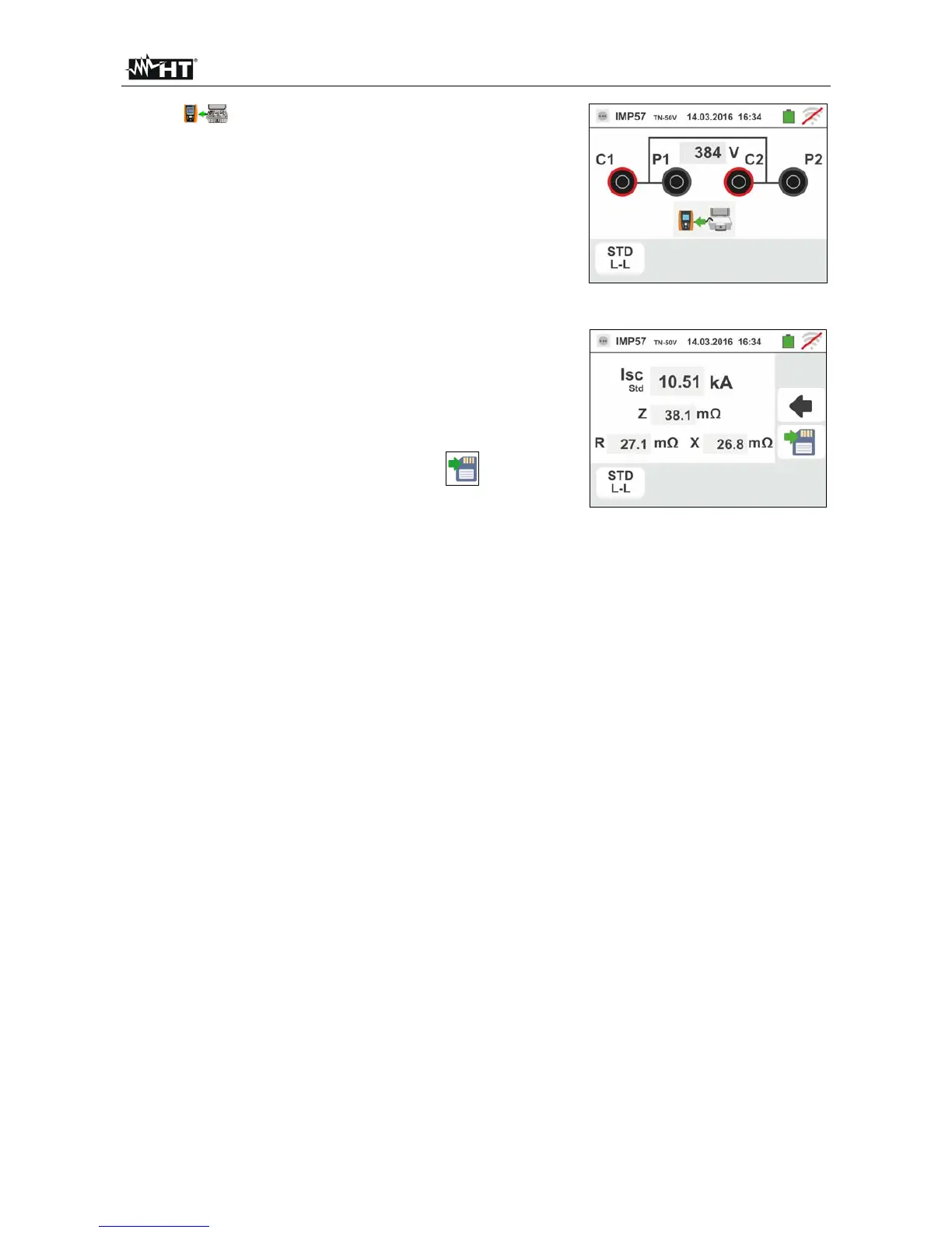
The symbol indicates the correct connection and
recognition of the IMP57 by the instrument. Check the
green STATUS LED lighting on the IMP57.
The value of the voltage between the measurement
points is shown in the upper part of the display.
Press the GO/STOP key on the instrument to start the
test. The following screen is shown on the display (in
case of L-L measurement in STD mode)
5. The standard (STD) short-circuit current is shown in the
upper part of the display.
The P-P Loop impedance values, in addition to its
resistive and reactive components, are shown in the
central part of the display, expressed in m.
Press the SAVE button or touch the icon to save
the measurement (see § 7.1).