5.3. LOWΩ – SETTINGS FOR CONTINUITY TEST WITH 200MA
The purpose of this measurement is to test the continuity of protective conductors and
equipotential ones (e.g. from rod to earth and connected foreign earth) and earth rods of
SPDs on PV installations. The test must be carried out using a test current > 200mA
according to the prescriptions of IEC/EN62446 guideline
5.3.1. Instrument settings
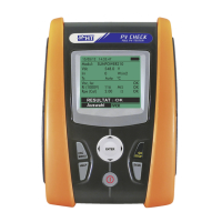
1. Position the cursor onto LOWΩby using the arrow keys
and confirm with ENTER. The display shows the following
screen:
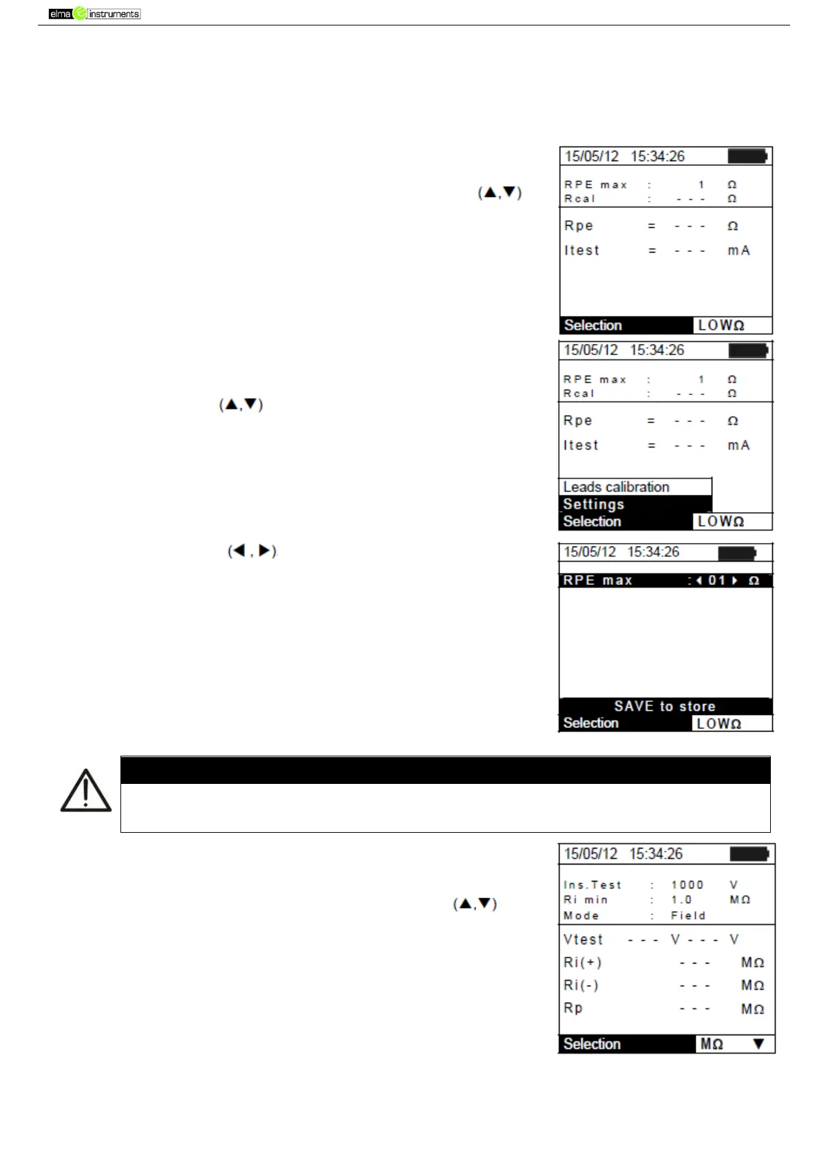
2. Press the ENTER key. The instrument shows the following
options: Settings and Leads calibration
3. Use the arrow keys to select “Settings” and confirm with
ENTER. The instrument shows the following screen:
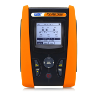
4. Using the arrow keys it is possible to set the maximum
limit value of Rpe resistance which the instrument uses as a
reference while measuring.
5. Press the SAVE key to save the settings made; the message
“Data saved” will be displayed for a few seconds. Press the
ESC/MENU key to exit without saving and go back to the
previous screen.
select “Settings” and confirm with ENTER. The instrument shows the following screen:
The settings saved for max RPE also affect the settings for the Continuity test
contained in the IVCK measurement (MENU IVCK)
5.4. MΩ – SETTINGS FOR INSULATION MEASUREMENT
5.4.1. Instrument settings
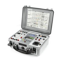
1. Position the cursor onto MΩby using the arrow keys and
confirm with ENTER. The display shows the following screen: