Upon pressing the GO/STOP key, different error messages can be displayed by the
instrument (see § 6.6) and, therefore, the test cannot be started. Check and eliminate, if
possible, the problem causing the error message before going on with the test.
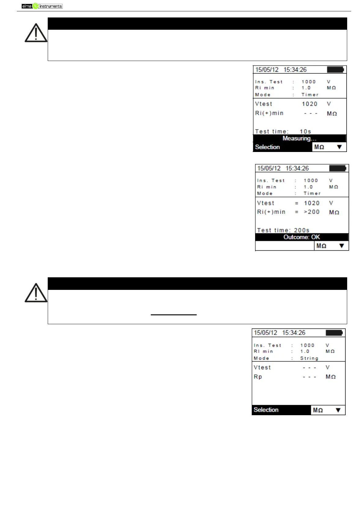
4. Press GO/STOP to start the test. In case no error conditions occur,
the instrument displays the message “Measuring…” as shown in
the screen to the side.
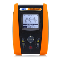
5. When measurement is complete, the instrument provides the
Ri(+)min value, i.e. the minimum value of insulation resistance of
the PV module/string (or of other metal masses) being tested,
continuously measured during the whole duration of measurement.
If the result is higher than the minimum limit set, the instrument
displays the message “Outcome:OK”; otherwise, it displays the
message “Outcome:NO” as shown in the screen to the side.
6. Press the SAVE key to store the test result in the instrument’s
memory (see § 7.2) or the ESC/MENU key to exit the screen
without saving and go back to the main measuring screen.
6.4.4. Measuring insulation – STRING mode
The maximum current which can be measured by the instrument is 10A. Before
carrying out the measures of Insulation in "STRING" mode, always ensure that the
instrument is connected to ONE STRING and not more strings in parallel to avoid
possible damage of it
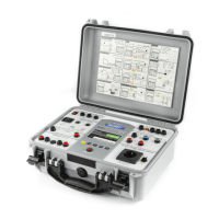
1. Position the cursor onto MΩ by using the arrow keys (,) and
confirm with ENTER. The display shows the screen to the side.
2. Press the ENTER key, activate “Settings” and possibly change
the desired parameters (see § 5.4). The following parameters are
shown on the display:
Ins. Test selected test voltage (250, 500 or 1000VDC)
Ri min minimum limit threshold for insulation measurement
Mode measuring mode: STRING
Vtest real applied test voltage
Rp final value of the measurement obtained by the parallel
of Ri(+) e Ri(-) values which is compared with the Ri min limit
by the instrument
key access to the second page with the measured values
of VPN, VEP and VEN voltages
3. Connect the instrument to the PV module/string being tested and to the main earth node of the
system as shown in. In particular, connect the negative output pole of the PV field to terminal N
and the positive output pole of the PV field to terminal P.