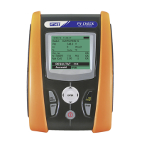
Fig. 13:Compensation of the
measuring cables’ resistance
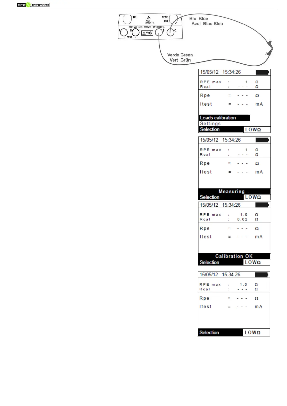
2. Press the ENTER key. The instrument shows the following
options: Settings and Leads calibration
3. Use the arrow keys (,) to select “Leads calibration” and
confirm with ENTER.
4. Press GO/STOP to start calibration. The message “Measuring…”
is shown on the display.
5. At the end of the compensation procedure, in case the measured
value of resistance is lower than 5, the instrument gives out a
double sound to signal the positive result of the test. The
following screen appears on the display:
6. The value of compensated resistance of the cables which will be
subtracted from all subsequent continuity measures is shown next
to “Rcal” and the message “Calibration OK” appears on the display.
7. To delete the value of compensated resistance, carry out a new
compensation procedure with a resistance higher than 5Ω such as,
for example, with open leads. The value in Rcal is zeroed on the
display.
6.5.3. Measuring continuity
1. Position the cursor onto LOWΩ by using the arrow keys (,)
and confirm with ENTER. The display shows the screen to the
side.
2. Press the ENTER key, activate “Settings” and possibly change
the desired parameters (see § 5.3.1). The following parameters
are shown on the display:
RPE max maximum threshold for continuity measurement,
which can be selected in a range 1Ω ÷ 5Ω in steps of 1Ω
Rcal the value of resistance of the measuring cables after
calibrating them
Rpe the result of continuity measurement
Itest real test current
3. Press the ENTER key, activate “Cable calibration” (see § 6.5.2) to carry out the initial calibration
of the measuring cables.
Connect the instrument to the PV module/string being tested and to the main earth node of the
system as shown in