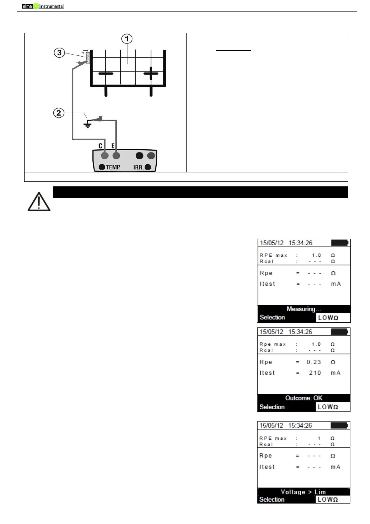
4. Fig. 14
CAPTION:
E: Green cable
C: Blue cable
1. PV module/string
2. Main system earthing
3. Earthed metal structure in
the system
Fig. 14: Connection for continuity measurement on structures of the PV installation
Upon pressing the GO/STOP key, different error messages can be displayed by the
instrument (see § 6.6) and, therefore, the test cannot be started. Check and eliminate, if
possible, the problem causing the error message before going on with the test.
5. Press GO/STOP to start the test. In case no error conditions
occur, the instrument displays the message “Measuring…” as
shown in the screen to the side.
6. At the end of measurement, the instrument provides the value of
resistance of the object being tested. If the result is lower than
the maximum limit set, the instrument displays the message
“Outcome:OK”; otherwise, it displays the message
“Outcome:NO” as shown in the screen to the side.
7. Press the SAVE key to store the test result in the instrument’s
memory (see § 7.2) or the ESC/MENU key to exit the screen
without saving and go back to the main measuring screen.
6.5.3.1. Anomalous situations
1. In case the instrument detects a voltage higher than 5V at its
terminals E and C, it does not carry out the test, gives out a long
sound and displays the message “Voltage > Lim”.