6.4.2. Measuring insulation – FIELD mode
1. Position the cursor onto MΩ by using the arrow keys (,) and
confirm with ENTER. The display shows the screen to the side:
2. Press the ENTER key, activate “Settings” and possibly change
the desired parameters (see § 5.4). The following parameters are
shown on the display:
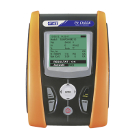
Ins. Test selected test voltage (250, 500 or 1000VDC)
Ri min minimum limit threshold for insulation measurement
Mode measuring mode: FIELD
Vtest real test voltages applied respectively between the
Positive pole and the Negative pole of the field respect the
earthing
Ri (+) insulation resistance measurement between the
Positive pole of the PV field and the earthing
Ri (-) insulation resistance measurement between the
Negative pole of the PV field and the earthing
Rp final value of the measurement obtained by the parallel
of Ri(+) e Ri(-) values which is compared with the Ri min limit
by the instrument
key access to the second page with the measured values of VPN, VEP and
VEN voltages
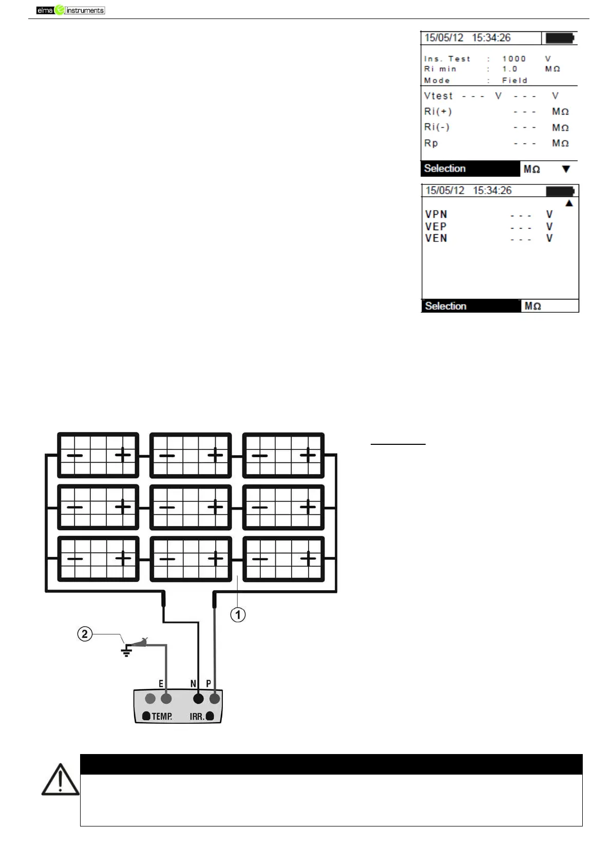
3. Connect the instrument to the PV field being tested and to the main earth node of the system
shown in Fig. 10. In particular, connect the negative output pole of the PV field to terminal N and
the positive output pole of the PV field to terminal P.
CAPTION:
E: Green cable
P: Red cable
N: Black cable
1. Unearthed PV field
2. Main system earthing
Fig. 10: Instrument connection for insulation measurement in FIELD mode
Upon pressing the GO/STOP key, different error messages can be displayed by the
instrument (see § 6.6) and, therefore, the test cannot be started. Check and eliminate, if
possible, the problem causing the error message before going on with the test.