PVCHECKs-PRO
EN - 43
SOLAR03 active and connected or active and recording
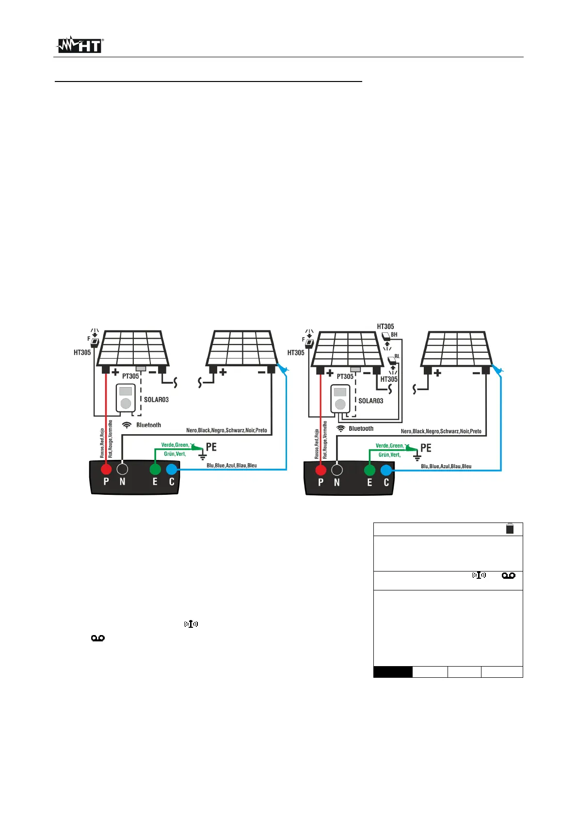
1. Connect the instrument to the PV module/string being tested and to the main earth
node of the system, and to the metal masses connected to earth as shown in Fig. 11.
In detail:
Connect the negative output pole of the PV module/string to terminal N and the
positive output pole of the PV module/string to terminal P.
In case of Monofacial modules position the reference cell HT305 onto the front
surface of module (F) and at input “INP1” and possibly temperature probe PT305
at input “INP4” of the remote unit.
In case of Bifacial modules position the 3 reference cells HT305 onto the front
surface of module (F), onto the back top part (BH=BackHigh) and onto the back
bottom part (BL=BackLow) of the module. Connect the front reference cell (F) to
input “INP1”, BH reference cell to input “INP2”, BL reference cell to input “INP3” and
possibly the temperature probe PT305 to input “INP4” of the remote unit.
Check reading of irradiance and temperature values on the remote unit SOLAR03.
2. If necessary, select option “><” and confirm with ENTER. Carry out a possible
calibration of cables as described in § 6.3.1.
Fig. 11: Connection with remote unit SOLAR03 on Monofacial and Bifacial modules
3. Position the cursor onto IVCK by using the arrow keys
(,) and confirm with ENTER. The display shows the
screen to the side: The following parameters are shown:
Irr. Irradiance values measured by cell HT305
connected to the remote unit
Temp. Temperature value of module
Remote unit indications on the serial number,
connection status “ ” and possible ongoing recording
“ ” of the remote unit SOLAR03 connected and
active.
ISO minimum limit for insulation measurement
RPE maximum limit for continuity test
>< value of calibration resistance of cables for
continuity test
Values of voltages VPN, VPE and VNE
IVCK 15/10 – 18:04
Front
Irr. 920 W/m2
Temp. 54.7 °C
SOLAR03 23051203
Module: SUNPOWER318WTH
VPN VPE VNE
1480V 740V -740V
1000V 1.00M 2 0.25
VTest ISO RPE
><