2. Lead the other end through the cable outlet module on the right at the bottom of the OMB,
and then route the cable to external power equipment. For details about how to install a
cable outlet module, see 10.4.2 Installing a Cable Outlet Module in an OMB.
Step 2 Route the cable by referring to 10.4.1 Cabling Requirements, and then use cable ties to bind
the cable.
Step 3 Label the installed cables. For details, see Attaching a Cable-Tying Label.
----End
Installing a BBU Power Cable
When AC power is fed into a DBS3900, a BBU power cable feeds power into the BBU from a
power equipment (AC/DC). A BBU power cable feeds power into a BBU.
Context
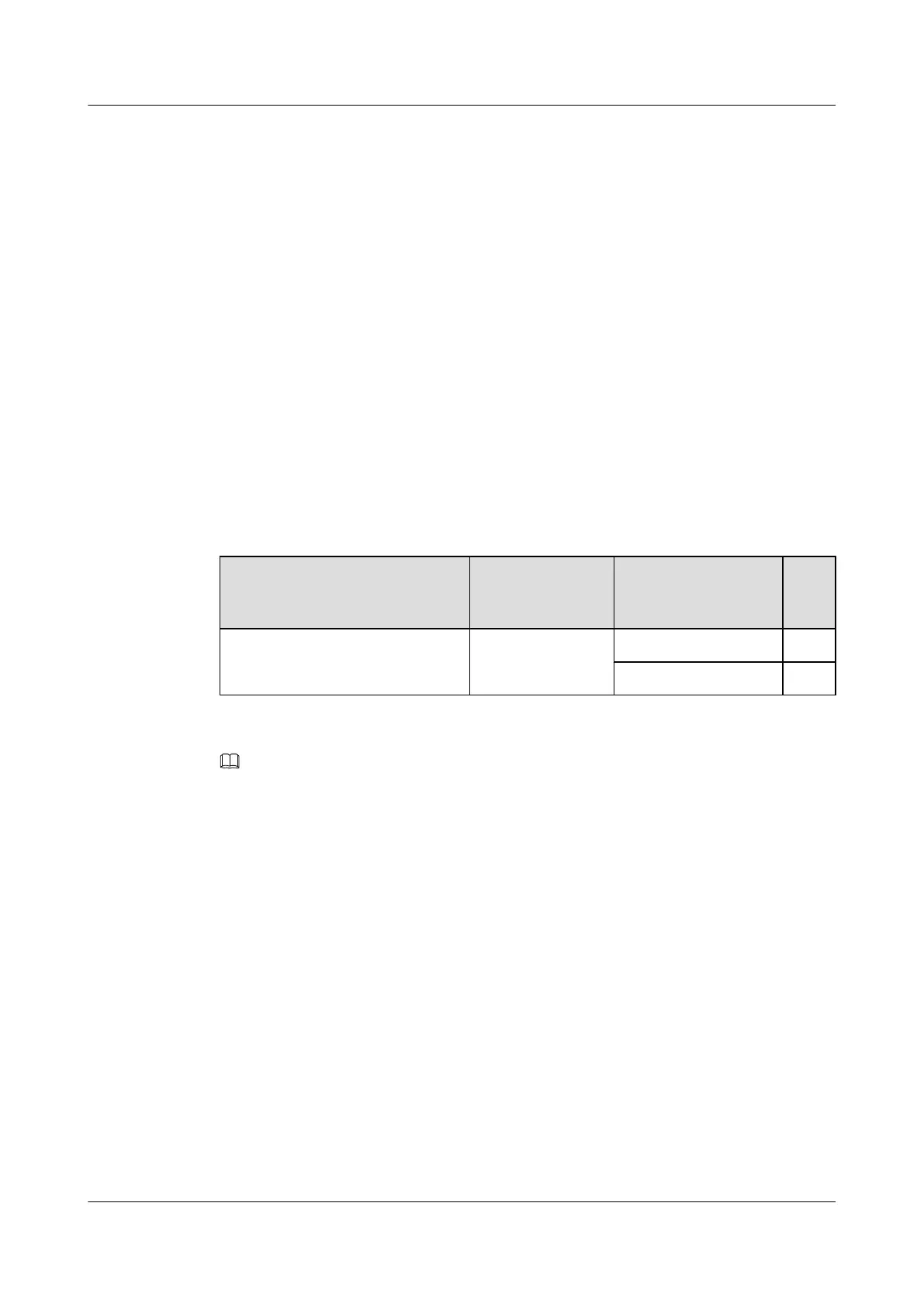
Table 10-3 lists the specifications of a BBU power cable when a power cable (AC/DC) supplies
power. For details about a BBU power cable, see BBU Power Cable (OMB).
Table 10-3 Specifications of a BBU power cable
Cable One End The Other End Des
cript
ion
BBU power cable [power supplied
from a power equipment (AC/DC)]
H4 connector 3V3 power connector
3V3 power connector
NOTE
The colors and structures of cables vary according to countries and areas. If the cables are purchased locally,
the colors and structures of the cables may be different.
Procedure
Step 1 Install a BBU power cable, as shown in Figure 10-21.
1. Link the H4 connector at one end of the BBU power cable to the DC output wiring terminal
labeled LOAD1 on the power equipment (AC/DC).
2. Link a 3V3 power connector at the other end to the -48 V port on the UPEU in the BBU,
and then tighten the screws on the connector until the tightening torque reaches 0.25 N·m.
3. Link another 3V3 power connector at the other end to the DC INPUT port on the HEUA.
DBS3900 (Ver.B)
Installation Guide
10 Outdoor Scenario with AC Power Supply (BBU Installed
in an OMB)
Issue 06 (2011-09-15) Huawei Proprietary and Confidential
Copyright © Huawei Technologies Co., Ltd.
346