Figure 12-7 Installing a WGRU PGND cable
NOTE
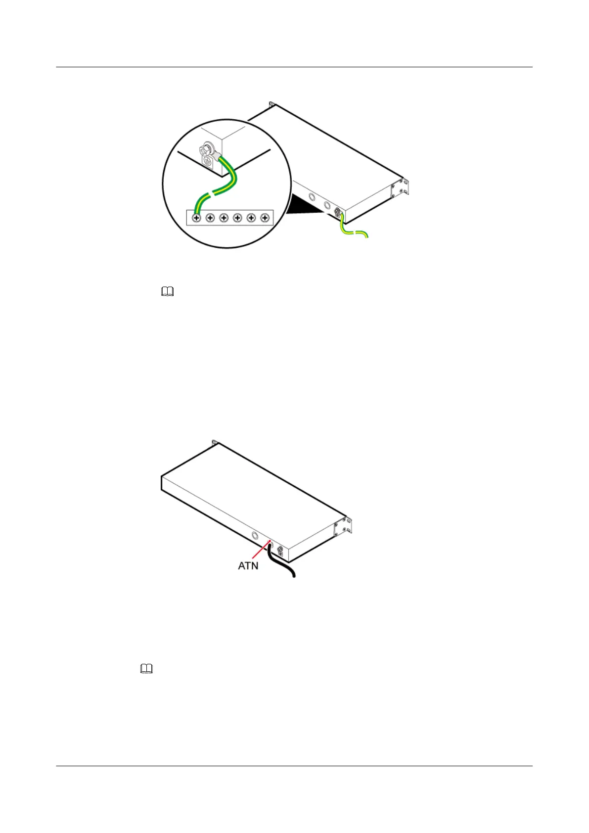
The WGRU PGND cable is connected to the closest ground bar.
4. Route the cable by referring to 12.4.1 Cabling Requirements, and then use cable ties to
bind the cable.
Step 3 Install a GPS clock signal cable.
1. Link the N-type female connector at one end of the GPS clock signal cable to the ATN port
on the back panel of the WRGU, and then link the SMA male connector at the other end
to the GPS antenna, as shown in Figure 12-8.
Figure 12-8 Installing a GPS clock signal cable
2. Route the GPS clock signal cable upwards along the column of the cabinet, and then use
cable ties to bind the cable securely. For details, see 12.4.1 Cabling Requirements.
Step 4 Install a WGRU power cable.
NOTE
A 2-hole male connector is added to one end of a WGRU power cable, and you only need to add an OT terminal
at the other end.
1. Cut the cable to the required length based on the actual cable route.
2. Add an OT terminal to one end of the cable. For details, see Assembling the OT Terminal
and the Power Cable.
DBS3900 (Ver.B)
Installation Guide
12 Indoor Scenario with DC Power Supply (BBU Installed in
a 19-Inch Rack)
Issue 06 (2011-09-15) Huawei Proprietary and Confidential
Copyright © Huawei Technologies Co., Ltd.
409