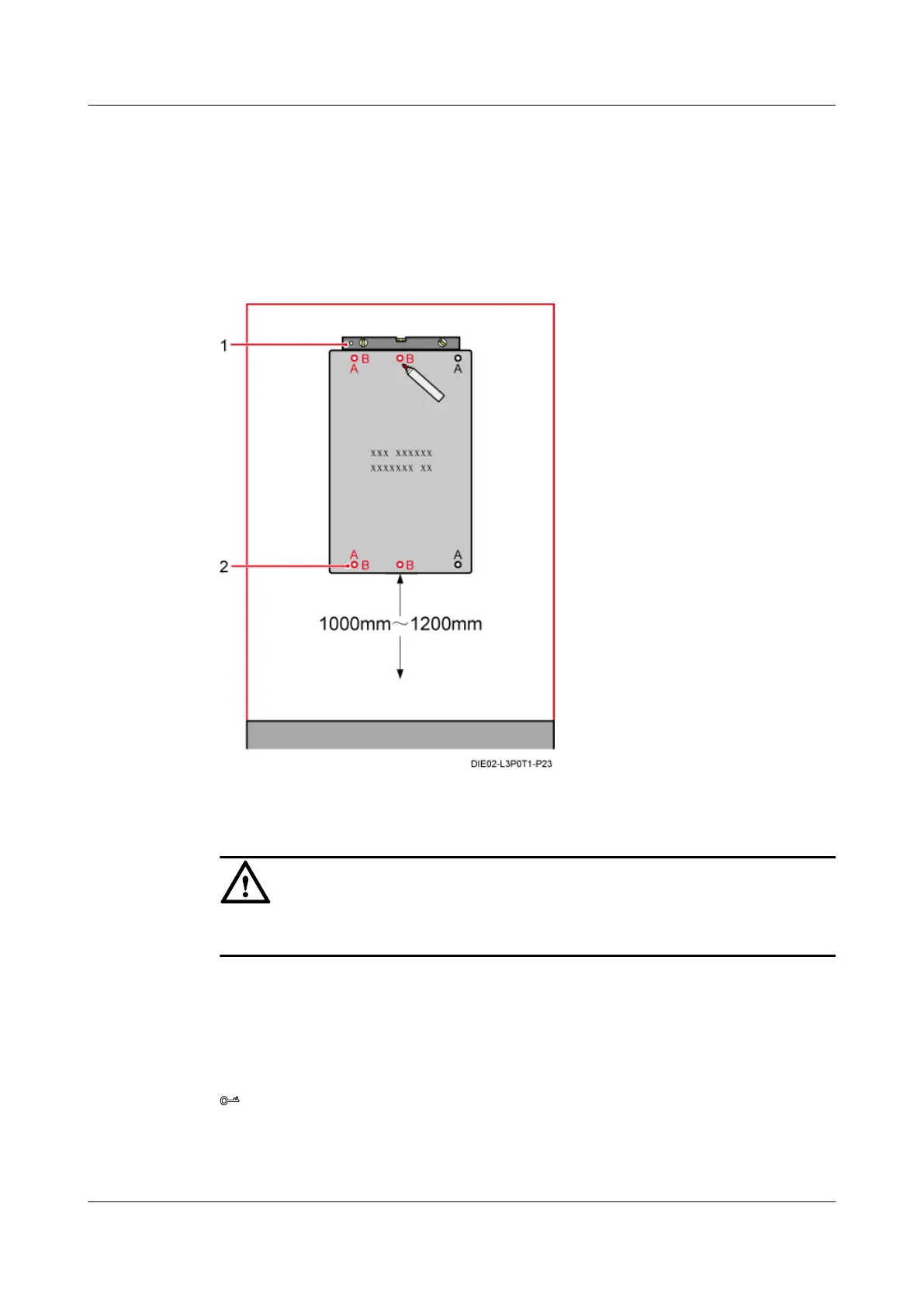
Step 4 Use a level to check that the two anchor holes on the marking template are on a horizontal plane,
place the marking template against the wall, and then use a marker to mark anchor points, as
shown in Figure 13-22.
Holes marked "B" are used as anchor points. The distance between the marking plate and the
ground is 1000-1200 mm.
Figure 13-22 Marking anchor points
(1) Level (2) Anchor holes
CAUTION
The bolts in the wall must bear a stress of a minimum of 1.25 kN.
Step 5 Drill holes at the anchor points, and then install expansion bolt assemblies, as shown in Installing
the IMB03 on the Wall (Side-Mounted).
Step 6 Place the IMB03 onto the two bolts at the upper anchor points, and then use a torque wrench to
pre-tighten the two bolts until a 20-30 mm length of each bolt is reserved out of the wall, as
shown in Figure 13-23.
TIP
Tighten the two bolts at the lower anchor points prior to the bolts at the upper anchor points, and ensure
that the subrack is vertical.
DBS3900 (Ver.B)
Installation Guide 13 Indoor Scenario (BBU Installed in an IMB03)
Issue 06 (2011-09-15) Huawei Proprietary and Confidential
Copyright © Huawei Technologies Co., Ltd.
449