Step 8 Take a spare PCIe card out of its ESD bag.
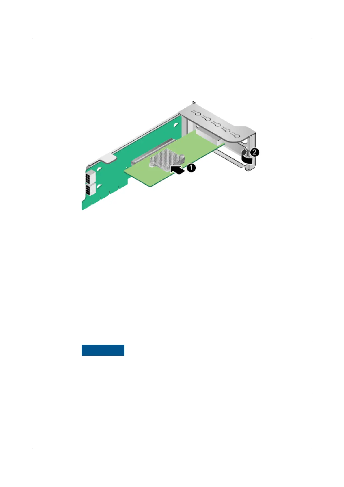
Step 9 Insert the PCIe card into a PCIe slot. See (1) in Figure 5-58.
Step 10 Close the latch. See (2) in Figure 5-58.
Figure 5-58 Installing a PCIe card on a riser module
Step 11 Install the riser module. For details, see 5.11 Riser Module.
Step 12 Install the chassis cover. For details, see 5.8 Chassis Cover.
Step 13 Install the server. For details, see 5.4.3 Installing the Server on Guide Rails.
Step 14 Connect the power cables. For details, see 5.7 PSU.
Step 15 Power on the server. For details, see 5.4.1 Powering On the Server.
Step 16 Log in to the iBMC WebUI, and check whether the new component is normal. For
details, see the
TaiShan Rack Server iBMC User Guide
.
----End
5.13 Battery
This section uses the server with Kunpeng 920 7260, 5250, or 5230 processors as
an example to describe the internal structure of a server. The procedures for
removing and installing the battery are the same for the server
congured with
Kunpeng 920 5220 or 3210 processors.
Removing the Battery
Step 1 Wear an ESD wrist strap. For details, see 5.2 ESD Protection.
Step 2 Power
o the server. For details, see 5.4.2 Powering O the Server.
TaiShan 200 Server
Maintenance and Service Guide (Model 2280) 5 Removal and Installation
Issue 04 (2020-01-16) Copyright © Huawei Technologies Co., Ltd. 121

 Loading...