Pub. 42004-550A
Elemec3 Console Manual—Version 3.0 Page 59 of 114
P:\Standard IOMs - Current Release\42004 Instr. Manuals\42004-550A.docx
09/20
Outputs Tab
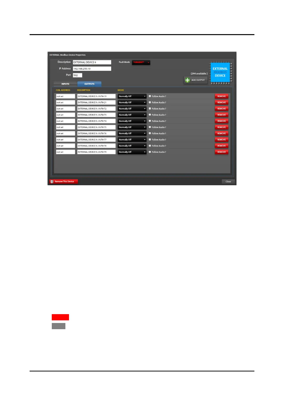
Figure 62. External Modbus Device Properties/Outputs
Coil Address—address of the discrete output on the field device (Modus server). Refer to the
manufacturer user manual to obtain this information.
Description—a unique description of the output function (i.e. red beacon activation, open entry gate, etc.)
Mode:
• Disabled—The output is unused.
• Normally ON—The output (Modbus coil) is ON (data = FF00) when the event is inactive. The
output (Modbus coil) is OFF (data = 0000) when the event is active.
• Normally OFF—The output (Modbus coil) is OFF (data = 0000) when the event is inactive. The
output (Modbus coil) is ON (data = FF00) when the event is active.
Follow Audio—assuming the event is a playback type, the output (Modbus coil) will change from its
normal ON/OFF state only while the playback audio is broadcasting.
1. Use the ADD OUTPUT button to add and configure additional outputs.
2. Configure the COIL ADDRESS, DESCRIPTION, MODE, and FOLLOW AUDIO? properties for each
output in the list.
3. Click REMOVE on any output to remove that output definition from the system.
4. Click CLOSE to return to the MODBUS SUMMARY screen.
NOTE: Refer to the Modbus field device manual for Modbus mapping parameters that define the
available data, data addresses, and data types. Configure the ADDRESS, DESCRIPTION, MODE,
and FOLLOW AUDIO? properties for each input in the list.

 Loading...