BALANCING PROCEDURES 35
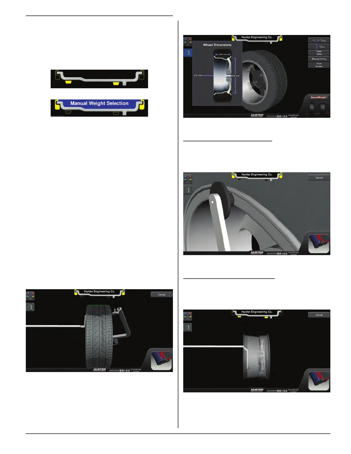
Dimensions can be viewed by touching the Dimension
button.
Figure 125.
Dimensions Entry - Inner Clip
Lifting only the inner Dataset® arm signals to the
balancer that the operator wants to measure an inner
plane clip dimension.
Figure 126.
Dimensions Entry - Inner Tape
Pulling out only the inner Dataset® arm and pointing it
down signals to the balancer that the operator wants to
measure an inner plane tape dimension.
Figure 127.
3.9 Balancing Procedures for Specific
Weight Types and Placement using
TruWeight™
The SmartWeight Touch®/GSP9200 Touch offers both
automatic and manual modes for weight placement.
Figure 122. Automatic Mode
Figure 123. Manual Mode
Clip-clip, tape-tape and mixed weight modes are
available for both dynamic and static balancing.
With these options, correction weights can be placed at
an infinite number of locations, based upon the choice of
the operator.
Automatic is the default setting, automatically choosing
the correct type of weights and locations determined by
the placement of the Dataset® arms.
TruWeight™ shows the operator exactly how to place the
weights on the wheel. Place them exactly as displayed on
the screen.
Dimensions Entry
From the main balance screen, the operator can take
wheel dimensions. This is done by either lifting the inner
Dataset® arm or lowering the outer Dataset® arm.
In both cases, the on-screen graphics will match the
movement of the arms.
Figure 124.
The action of positioning the Dataset® arms sets the
corrective weight types and locations the operator
chooses. The balancer will now display those types and
locations during the balance procedure.