54 Automower from
3. Installation
™
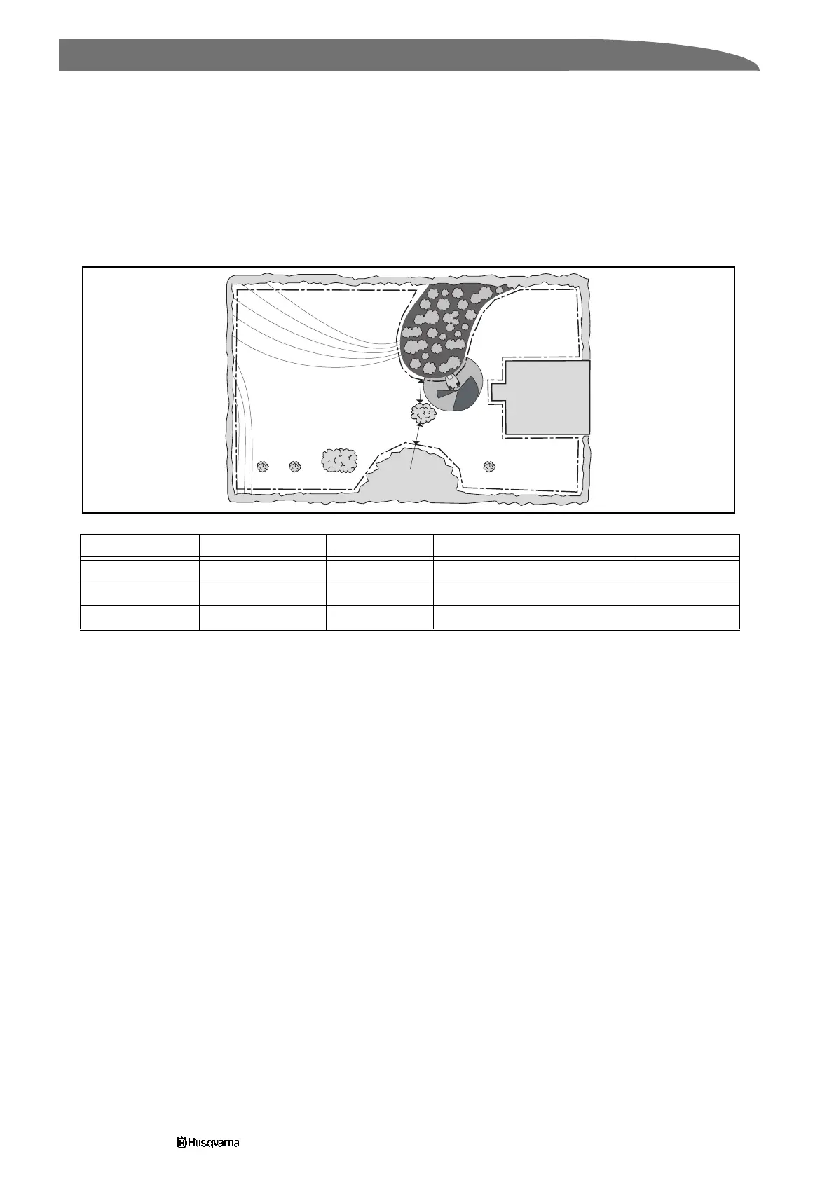
Example number 3
In this example different exit angles have been set. Automower will easily reach all parts of the working
area. The risk of tracks forming is less with these settings compared with allowing the mower to follow the
boundary wire out of the charging station.
Increasing the delay time for the boundary wire increases the chance of the mower finding the charging
station before it starts to follow the boundary wire. When searching it is a disadvantage for the mower to
follow the boundary wire across an incline.
Follow loop Boundary wire Guide wire Exit angles Area 1, 2, 3
Delay 20 minutes 7 minutes Start angle 1 – End angle 1 (3) 60° and 200°
Corridor width 6 6 Start angle 2 – End angle 2 (1, 2) 240° and 270°
Proportion first 40%
3012-625
3m
2
3m
1
Fully approved
3
 Loading...