TroubleshooTing and sysTem TesTs
powermax
45
Service Manual 5-7
4. Remove the Mylar barrier from the power board side of the power supply. Be certain to replace the barrier when
you are finished working on the power supply.
5. Inspect the inside of the power supply, especially on the side with the power board. Look for broken or loose
wiring connections, burn and char marks, damaged components, and so on. Repair or replace as necessary.
Initial resistance check
All resistance values must be taken with the power cord disconnected and all internal power supply wires attached.
Perform the steps in Internal inspection on page 5-6 before continuing in this section.
• If resistance values are not close (±25%) to the values given in this section, isolate the problem by removing wires
attached to the resistance check points or component until the problem is found.
• After the problem has been located and repaired, refer to the Sequence of operation flow diagram on page 5-4
to test the power supply for proper operation.
1. With the power disconnected and the torch removed from the power supply, set the ON/OFF switch(S1) to
ON(I).
2. Check the resistance across the input leads (the leads are identified with “AC” printed on the power board).
• 200–240V CSA and 230V CE: resistance across the input leads = 75kΩ.
• 400V CE and 480V CSA: resistance across the input leads = 2.5MΩ.
3. Check the resistance from the input leads to ground to verify that it reads as open. For all power supplies, the
resistance from input to ground should read as > 20MΩ.
Note: With the power disconnected and the ON/OFF switch(S1) set to OFF(O), all circuits should read
asopen.
The electrical values shown are ±25%.
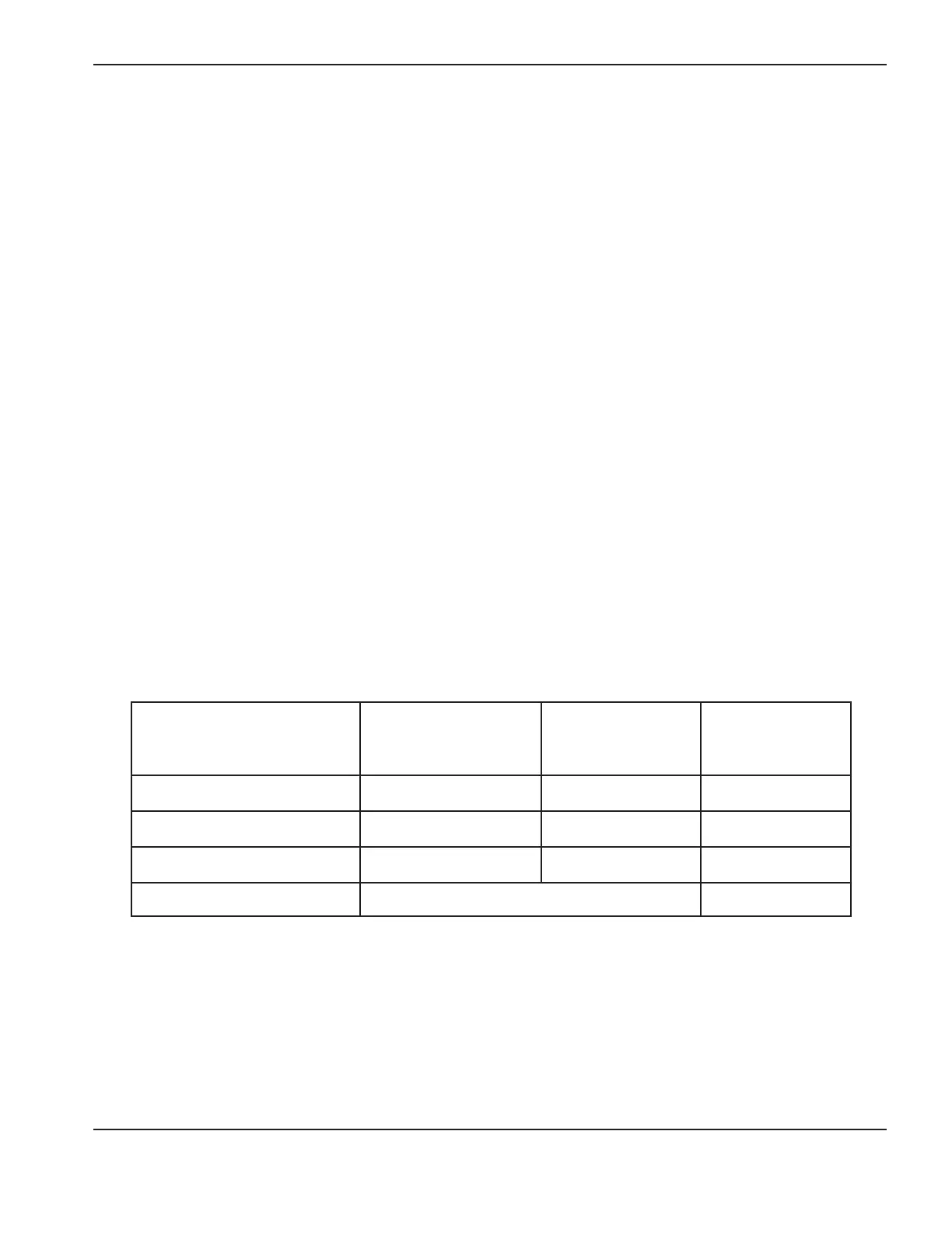
4. Check the output resistance for the values shown in the following table.
Measure resistance from
200–240V CSA and
230V CE power board
location
400V CE and 480V
CSA power board
location
Approximate
values
Work lead to nozzle J21 to J17 J21 to J16 100 kΩ
Work lead to electrode J21 to J19 J21 to J18 20 kΩ
Electrode to nozzle J19 to J17 J18 to J16 120 kΩ
Output to ground > 20 MΩ
If no problems were found during the visual inspection or the initial resistance check, and the power supply still does not
operate correctly, see the Troubleshooting guide on page 5-11.
Note: The Troubleshooting guide provides most probable causes and solutions. Study the system wiring diagram
and understand the theory of operation before troubleshooting. Before purchasing any major replacement
component, verify the problem with Hypertherm Technical Service or the nearest Hypertherm repair facility.