torch setup
powermax
45
Service Manual 3-27
Refer to the following table when connecting the Powermax45 to a torch height controller or CNC with a machine
interface cable.
Signal Type Notes
Connector
sockets
External cable
wires
Start (start plasma) Input
Normally open.
18VDC open circuit voltage at START
terminals. Requires dry contact closure to
activate.
3, 4 Green, black
Transfer
(startmachinemotion)
Output
Normally open. Dry contact closure when
the arc transfers.
120VAC/1A maximum at the machine
interface relay or switching device
(supplied by the customer).
12, 14 Red, black
Ground Ground 13
Voltage divider Output
Divided arc signal of 50:1 (provides a
maximum of 7V).
5(-), 6(+) Black(-), white(+)
Accessing raw arc voltage
Connecting a cable to the Powermax45 power board to bypass the voltage divider and access raw arc voltage must be
done by a qualified service technician.
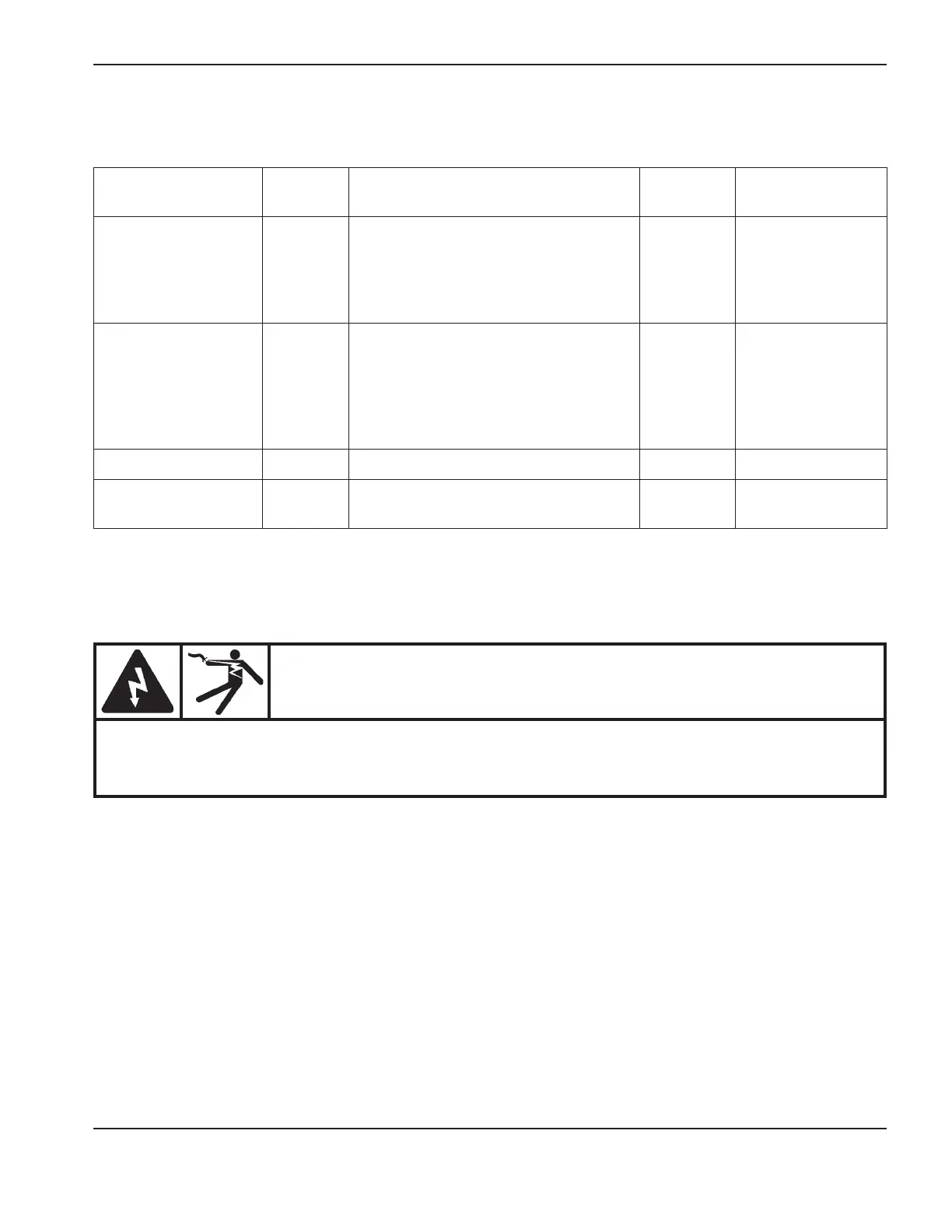
WARNING
HIGH VOLTAGE AND CURRENT
Connecting directly to the plasma circuit for access to raw arc voltage increases the risk of shock
hazard, energy hazard, and fire hazard in the event of a single fault. The output voltage and the
output current of the circuit are specified on the data plate.
To access raw arc voltage on a Powermax45, you will need kit number 228352 and an 18 AWG, 2 wire, non-shielded
cable similar to OLFLEX
®
190 (601802) in the length needed to go between the power supply and the CNC or other
equipment plus an additional 45.72cm (18 inches).
1. On the end of the cable that will be attached to the power supply, strip the outer jacket 11.43cm (4.5 inches). Cut
6.35cm (2.5 inches) off of wire2 so that wire1 is 11.43cm (4.5inches) long and wire2 is 5.08cm (2inches)
long. Then strip 1.27cm (0.5 inches) of wire insulation off of each wire.
2. Crimp a #8insulated ring on the end of wire1 and a #10insulated ring on the end of wire2.
3. Use a #2 Phillips screwdriver to remove the 2 screws from the handle on the top of the power supply. Tip the end
panels back slightly so that you can get the edges of the handle out from underneath them. Lift the cover off the
power supply. Remove the Mylar barrier that protects the power board.