PARTS
7-6 powermax
45
Service Manual
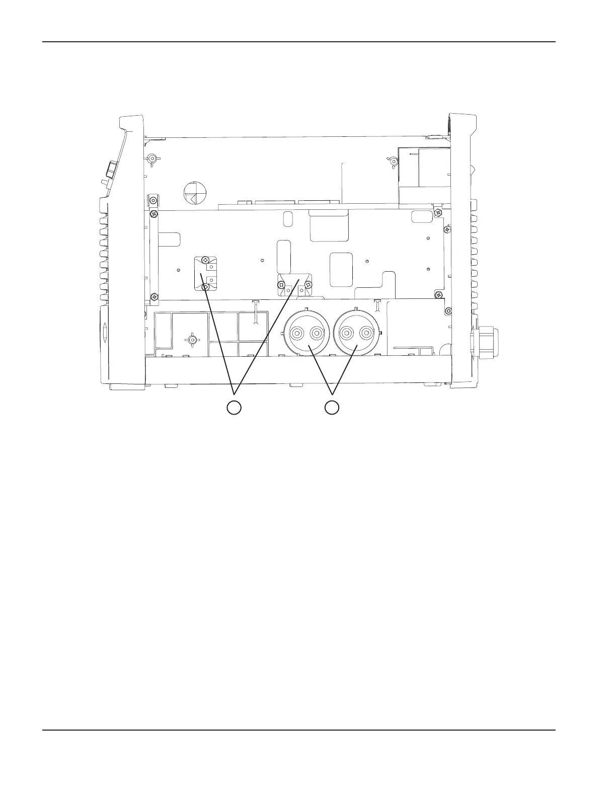
Interior, heat sink side
1
Item Part number Description Qty.
1 428065 Kit: Snubber resistors 2
2 228301 Kit: Capacitors, 200–240V CSA and 230V CE 2
228426 Kit: Capacitors, 400V CE 2
428080 Kit: Capacitors, 480V CSA 2