TroubleshooTing and sysTem TesTs
5-26 powermax
45
Service Manual
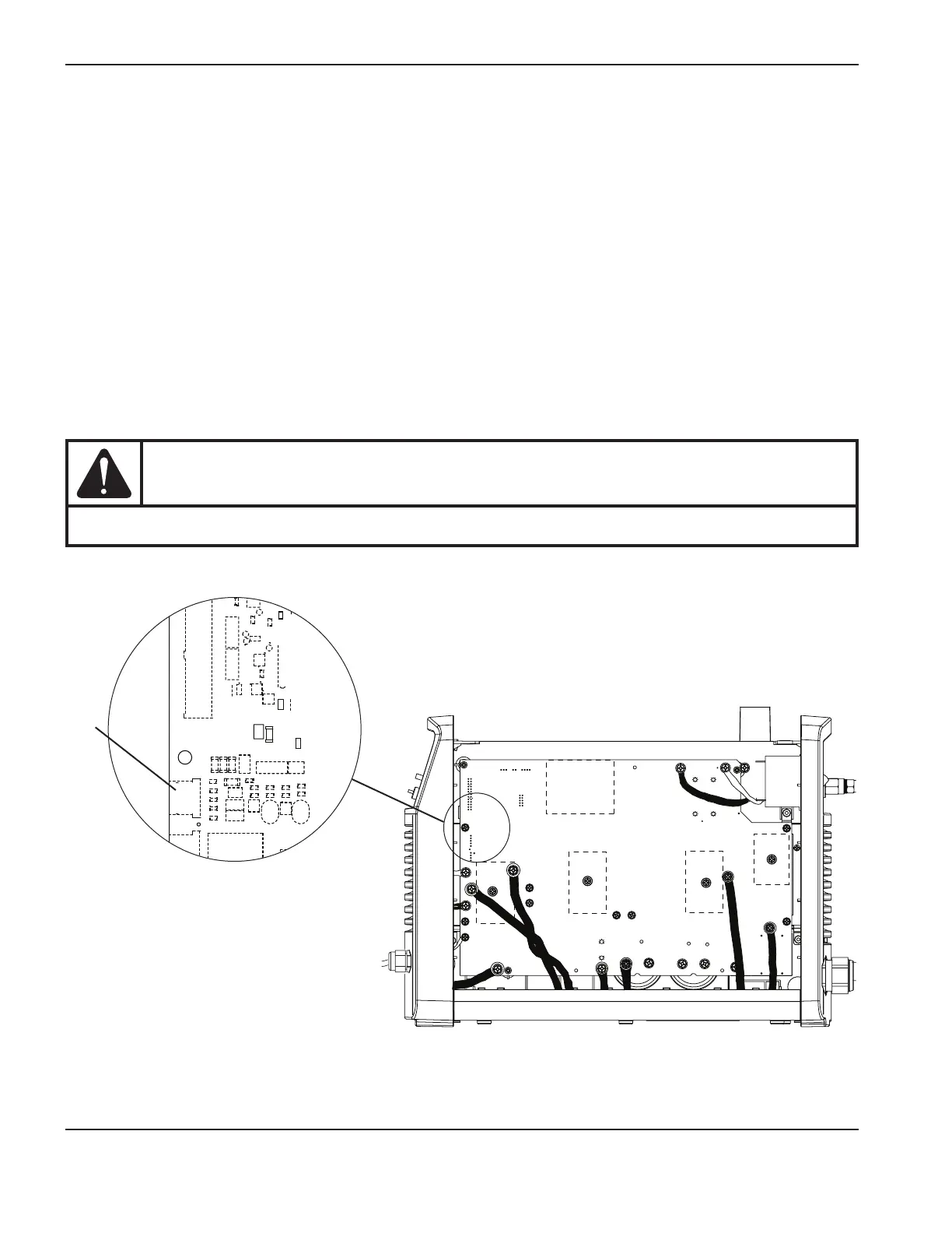
Test 6 – plasma start
Verify that the control board LED is receiving a valid start signal.
1. With the power ON, look at the Start LED on the control board. It should illuminate whenever the torch is
activated.
2. Set the ON/OFF switch to OFF(O). Check the resistance between pins2 and3 of J10 on the power board.
With the trigger or start signal engaged, the resistance should be 10Ω or less. With the trigger or start signal
disengaged, the circuit should read as approximately 3kΩ. If this test fails, check the torch’s start switch and the
torch wires.
NOTE: If the torch will not fire after completing this test, verify that J10 is connected properly – that the pins are
not offset and the connector is not backwards.
3. Set the ON/OFF switch to ON(I). Measure pin16 ofJ7 (or J8 for 400V CE and 480V CSA power supplies) to
ground (see Test 2 – power board voltage checks on page 5-19). It should measure as 0VDC for an open circuit
or 3.2VDC for a closed circuit. If the values are not correct, replace the power board.
CAUTION
While testing, remove the consumables to avoid accidentally firing the torch.
TP 19
W
-
+
-
+
TP 18
R
TP 17
B
192 VDC
192 VDC
J10